Hi ,
Built my other trapped horn today.now I have STEReO sub
here is the curve from Hornresp.
Its the best I could do with this driver (Perless Resolution 10) in 20 tryouts...?
I wonder if someone with experience of building these type of horn could tell me if it looks OK?
I sounds ok ..the peaks above 100hz is not disturbing and for the moment I have 2 conical pipes with a 6db lp passive filter at 50hz and for a room 60m2, I only use 1W and 10W at the peak.
I use these with Open baffles at the moment.
the sound is WERY loud and very clean and deep
VERY physical bass with volume above live level.
very open and Airy sounds almost as good to Heavy orck and ,Bjork as with jazz and acoustic music.
I used to have Jensen "Onken" 200litres box with 15" and thats was the best bass i had until now.
These are as good as the great klipsh cornerhorn and other big horn I have heard.
Its easy to become a bassfreak and overlevel these boxes..
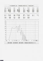
it is roughly flat from 30hz-100hz as far as i can make out
i would like to learn how to design horns is there a guide available on how to use the horn response program because all i see is a load of letter combinations that make little sense. basically it looks baffling at first but is probably simple when you learn it
thanks
i would like to learn how to design horns is there a guide available on how to use the horn response program because all i see is a load of letter combinations that make little sense. basically it looks baffling at first but is probably simple when you learn it
thanks
Naudio said:it is roughly flat from 30hz-100hz as far as i can make out
i would like to learn how to design horns is there a guide available on how to use the horn response program because all i see is a load of letter combinations that make little sense. basically it looks baffling at first but is probably simple when you learn it
thanks
check the wiki on this website
Take a look at the articles on the Danley Sound Labs web site and read the one about the SBG - the Sonic Boom generator (an Intersonics project for a government contract). It uses six 5 HP fans and a servomotor-controlled rotary valve to generate its acoustic output. This is off topic, but it deals with what you suggested - the fan subwoofer in a horn-type thing.
Wow the thread has become so Big ! After reading a few posts of those who have built this sub i am very interested in building this sub.
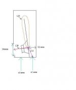
May i know which S1, S2, S3 ,S4 and the con ? It would really help if someone could point where or draw on the pic below to show where these lengths are in a tapped horn.
May i know which S1, S2, S3 ,S4 and the con ? It would really help if someone could point where or draw on the pic below to show where these lengths are in a tapped horn.
An externally hosted image should be here but it was not working when we last tested it.
An externally hosted image should be here but it was not working when we last tested it.
1. In the above pic is S3=L34 ?
2. Where is S4 suppose to be ?
3. S2 is the length from the back of the cone to the opening right ?
4. The blue line which is L23 is it suppose to be parallel to something and the how is the angle of the part indicated by pink arrow determined ?
Hi Buzzy,
are there missing labels?
I cannot see L34, is this from Rademakers' link?
Compare your diagram with Rademakers'.
We can see that at the middle of the horn path jast at the end of the dividing mid panel the sizes to each side of this baffle are very different between the two diagrams.
Look at Rade's, on the cone side the gap from baffle end to side panel is less than the baffle end to end panel.
The gap from baffle end to end panel is smaller than gap from baffle end to side panel with the mouth opening. i.e. as the sound wave goes around the corner the cross sectional area gets a little bit bigger to match the expansion of the rest of the route.
In Buzzy's diagram the cross sectional area appears to get smaller as the wave passes around the end of the baffle.
The reflectors should bounce the wave around the corner. They are not intending to maintain cross sectional area. At the very end the two reflectors should meet in the middle and be placed at 45degrees to the end panel (90degrees to each other). But in a horn where the expansion rate is fundamental to the operation of the wave flow this "normal" rule may not apply. The only way to test if constant or expanding cross-sectional area applies or if the reflector rule applies is to build a prototype and listen if the effect is audible.
Buzzy is referring to the values in HornResp.
Press F1 to pull up the help screen and go to page 3. You could also look here:
http://www.diyaudio.com/wiki/index.php?page=Hornresp+Help
Press F1 to pull up the help screen and go to page 3. You could also look here:
http://www.diyaudio.com/wiki/index.php?page=Hornresp+Help
Hi,
I see a question about speaker impedance earlier.
I have this idea in my head about horn impedance but it seems too good to be true.
Here goes.
If a horn is 50% efficient in it's passband, then half the input energy is dissipated as heat and the other half comes out as sound.
If the 50% that is dissipated as heat is all lost passing through Re then the other half of the input energy must be dissipated as sound driving the effective acoustic impedance of the "horn + driver". This assumes that the amp and cable resistance is near zero, but even 0.1ohms of total resistance in the drive end makes little difference to an 8ohm speaker.
Now let's assume that the Re of this 8ohm speaker is 6r0.
As stated earlier the acoustic impedance, in the passband, must also equal 6ohms (non reactive).
The total impedance seen by the amplifier is thus 12r0 (non reactive).
But horn response does not seem to show anything like this.
Where is my logic going wrong?
Can I assume that we must cut/filter the signal to the amplifier to ensure that the amp sends only a very attenuated signal that is outside the passband for any of the above to hold true?
There is probably going to be a follow up question on amplifier drive voltage once you have put me right on the above.
Hi Buzzy,
hopefully someone will draw a diagram for you.
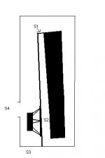
s1, 2, 3, 4 are the areas that are input into Hornresp at each change in taper/expansion rate.
s1 is at the start of the taper.
s2 is at the cone throat.
s3 is at the mouth where the other side of the cone sends it inverted phase pressure to join up with the delayed pressure wave that travelled along the horn.
s4 is the exit mouth.
Look at the distances in Hornresp.
s1 to s2 is very short. (Rade's diagram= L12)
s2 to s3 is long (R=L23)
s3 to s4 is short (R=L34)
Have I got the description right?
Should we break the taper up to show the discontinuous expansion around the bend/reflector?
hopefully someone will draw a diagram for you.
s1, 2, 3, 4 are the areas that are input into Hornresp at each change in taper/expansion rate.
s1 is at the start of the taper.
s2 is at the cone throat.
s3 is at the mouth where the other side of the cone sends it inverted phase pressure to join up with the delayed pressure wave that travelled along the horn.
s4 is the exit mouth.
Look at the distances in Hornresp.
s1 to s2 is very short. (Rade's diagram= L12)
s2 to s3 is long (R=L23)
s3 to s4 is short (R=L34)
Have I got the description right?
Should we break the taper up to show the discontinuous expansion around the bend/reflector?
- Home
- Loudspeakers
- Subwoofers
- Collaborative Tapped horn project