i just saw an error in my script. doesnt change much in the graph.
The 140 in the script should be a 141 like this, since the radiator needs to be at the end of the horn:
Radiator 'Rad1' Def='D20' Node=141 HD={xT} WD={x20}
Btw one can tap the driver into different places in the horn by changing the driver nodes:
Driver 'D1' Def='830500' Node=2=0=100=140
Node=100=140 is the end/beginning of the horn.
Node=110=130 would be just about in the middle.
putting the driver in the middle of the horn makes the bottom and top more peaky. end position seems to be better for flat response.
Hey Paul,
I think I posted my schematic for TH which is sorta hard to translate into an eclosure without a crossectional drawing representing the enclosure and showing the what portions of the eclosure are represented by the schematic.
The one thing that I can see in mavos script that I did and he did not do, Is I created a paralell path of nodes that flow from the rear of the driver back to the throat. I have not confirmation on weather the acoustic entities in ths program are uni directional or bi directional in terms of signal flow.
I basically used all ducts and Air masses.
I started by figuring out how the Band pass example in the manual was layed out.
I haven't dived to deep into the program yet I think there a lot of syntaxt that can be used that is not generated by the basic Value entry screens.
Where if you try and design a duct it needs you to figure the x sectional area and plug it in, where you can clearly see that in the bandpass example that, they are deriving the duct values from L x W x H. Perhaps the math becomes a little different if the ducts are calculated as rectangualr as opposed to a cross sectional equivalent???
Anyhow its not the simplest program to use. My advice is to start with your flow chart/schematic and then start trying to model it.
Good luck
Antone-
Looking at the exaple script in the AkAbak Manual on page 67 / 68 i figured, that ducts are two-directional. This corresponds with the duct element, which has four nodes. One input and one output for both directions, i assume. somewhere in the manual they mention that one only has to define two nodes for convenience, which could mean that the other two are mirrors. In the example they only use one duct for each physical part in the enclosure, even if sound can travel through it forward an backwards. Does this make sense?
Well I haven't tried the 4 node connection yet, but turning off the rear driver nodes certainly causes the graph to radically change.
One thing that I find Very Odd about my aKaBak preditions thus far is that,
The Driver tapped near the mouth model, resembles more closely my measures of the driver tapped near the center of the box.
and Vice Versa. I can't quite figure out why.
Antone-
One thing that I find Very Odd about my aKaBak preditions thus far is that,
The Driver tapped near the mouth model, resembles more closely my measures of the driver tapped near the center of the box.
and Vice Versa. I can't quite figure out why.
Antone-
Hi Patrick Bateman,
Do you have you any source for kippel and/or dumax measurements on Eminence LAB-12?
I am looking for these measurements.
I bought a pair of these a while back. If I build a tapped horn, I'm going to do it with the Diyma 12. It's Thiele-Small is comparable to the LAB 12, but it's superior in a few ways:
- it's cheaper
- it has more xmax
- it has a flatter BL curve
Do you have you any source for kippel and/or dumax measurements on Eminence LAB-12?
I am looking for these measurements.
Here are Z photos of my TH proto type
, no bracing at the moment It certainly needs it though!!
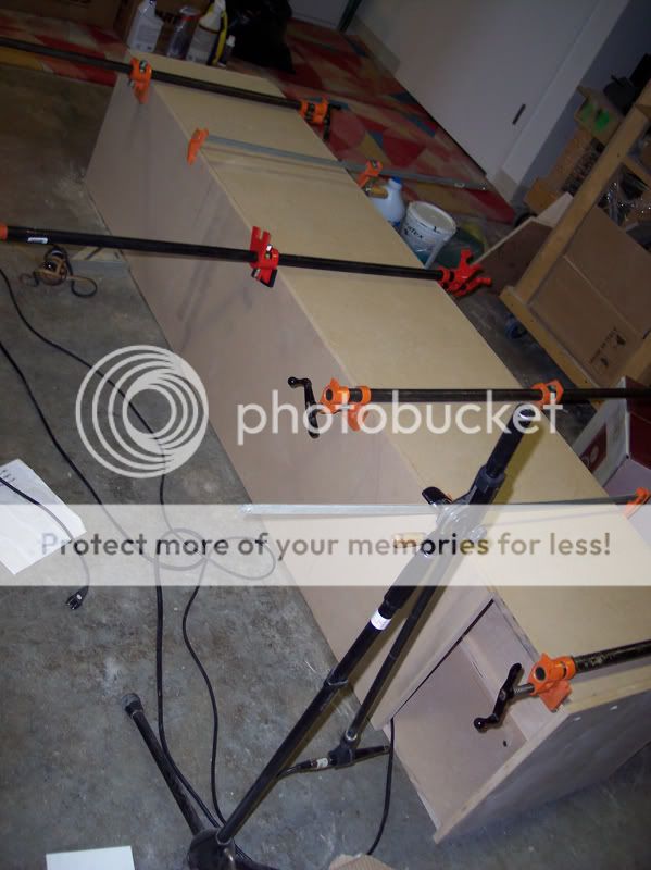
Any thoughts?
Antone-
, no bracing at the moment It certainly needs it though!!
An externally hosted image should be here but it was not working when we last tested it.
An externally hosted image should be here but it was not working when we last tested it.
Any thoughts?
Antone-
Me thinks perhaps the Third bend need to be a little bit longer??
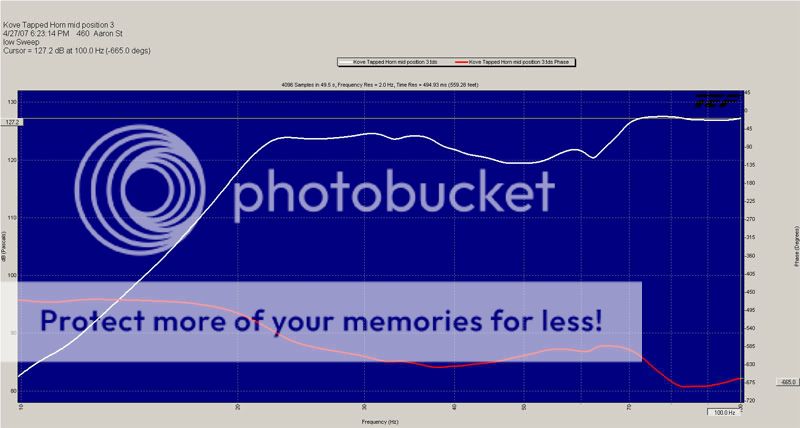
It is incredibly potent, down to the 22Hz knee. It doesn't seem to perform quite that great bellow the knee. At 20Hz the mechanical noise of the driver is noticable.
Here are the TS parameters I took from the Kove (Parts Express Buyout) Z12D I think.
dD=27.58cm |Piston
fs=49.7Hz
Mms=120.9g
Cms=0.0000848m/N
Rms=6.309Ns/m
Bl=21.03Tm
Qms=5.986
Qes=.555
Vas=.043m3
Re=6.5ohm
Le=1.595mH
ExpoLe=0.618
Xmax is ~18mm
Its a dual voice coil with 400Watts power handling per coil.
Anyone have any suggestions for alternative drivers.
Antone-
Antone, great to see your prototype! ")
Very interesting results also. I'm suprised to see how flat it is. I have a few questions for you:
1. What are the dimensions?
2. How far have you offset the driver from the mouth end?
3. How do you find excursion control below F3?
4. What efficiency 1w 1m did you find?
From what I've seen it is better to have the driver right in the mouth, yet your results for your prototype look great.
Great work. How did you find the SQ?
good grief Antone ! - response came out pretty darn good. ah - I see the specs above--diyma 12 has a lotta mass but might be good - strange to have dumax yet no qes & qms
since this tread is called collaborative TH project - will there be a project with currently available woofer? I have no experience with these type driver and your high fs Kove seemed to work well. Will Ciare's 12" drop in?
Freddy
since this tread is called collaborative TH project - will there be a project with currently available woofer? I have no experience with these type driver and your high fs Kove seemed to work well. Will Ciare's 12" drop in?
Freddy
Hey All,
Paul I'm not sure what you mean by SQ?
I started with The Outs side Dimensions of The DTS-20 and built the inside within those constraints. The driver is centered almost at 44" from mouth I think. I set the mouth to be ~10"
At 22.5HZ I'm predicting around 17mm and at 21.5Hz I'm predicting around 27.6mm
I haven't don the actual 1 W 1 meter I can give it a try ant the ware house but there is too much reflection in here. Everything I've done so far is a couple of inches from the mouth.
A thought occoured to me that the horn path dirrectly infront of the radiator may act as part of the actuall path length so perhaps I need to make it longer?
Freddi, I am going to have to revisit my aKabak to try and get it to resemble my results a little closer. The Ciare looks like it peaks a little more with a Higher F3.
It was a good start and I did ad 5 significant pieces of bracing to the internals plus a center hatch, IT STILL wasn't enough to really take care of issues up in the 60 and 70Hz range, as far as buzzing at high output. It was a lot of fun to remove the driver hatch while I was playing a 20Hz sine, it began oscilating up and down about 1/2 and inch.
Now all that I have to do is figure out how to make it road worthy for a Bass rig. I think I need apair Mu hah hah hahhhh!!
Antone-
freddi said:--diyma 12 has a lotta mass but might be good - strange to have dumax yet no qes & qms
Freddy
Maybe this will help:
An externally hosted image should be here but it was not working when we last tested it.
Frode
thanks Frode. Whats the story regarding cone rattling issues and where/when might that happen?
Freddy
http://www.diymobileaudio.com/forum/showthread.php?t=6613
Freddy
http://www.diymobileaudio.com/forum/showthread.php?t=6613
A different simulation. This time using a single waveguide as the main part. The driver is connected via ducts to it and the radiator. Perhaps this one is easier to understand then the last one i made. Better to play around with at least. It does modell slightly different then my other script (in the range of a few decibels here and there).
Is it accurate? I dont know, but it sure is interesting to play with. Would be nice if someone who has actual measurements of a real horn could tell me how accurate it is.
The Def_Const is where one can type in the horn dimensions. Xwidth is the width, which is constand for the whole horn. The throat area is defined by Xwidth*Xthroat. The mouth area is Xwidth*Xmouth. Lhorn is the horn length. Ldriver is the size of the driver. The dimensions are in centimeters (hence the e-2, since e0 would be meters).
Just copy paste everything below this sentence in an empty akabak script, hit f5 and click the OK button to see the frequency response.
Def_Const
{
Xwidth = 32e-2;
Xthroat = 10e-2;
Xmouth = 30e-2;
Lhorn = 450e-2;
Ldriver = 26e-2;
}
Def_Driver 'Lab12'
dD=25.2cm |Piston
fs=33Hz Mms=146g Qms=13.32
Bl=15Tm Re=4.29ohm Le=1.48mH ExpoLe=0.618
Driver 'D1' Node=2=0=100=101 Def='Lab12'
Duct 'Dr' Node=101=102 WD={Xwidth} HD={Xthroat} Len={Ldriver}
Duct 'Dd' Node=100=104 dD={Ldriver} Len=3cm
Duct 'Df1' Node=103=104 WD={Xwidth} HD={Xmouth} Len={Ldriver/2}
Duct 'Df2' Node=104=105 WD={Xwidth} HD={Xmouth} Len={Ldriver/2}
Waveguide 'W1' Node=102=103 WTh={Xwidth} HTh={Xthroat} WMo={Xwidth} HMo={Xmouth}
Vf=50mm3 Len={Lhorn-Ldriver-Ldriver} Conical
Radiator 'Rad1' Node=105 Def='Df2' WD={Xwidth} HD={Xmouth}
- Home
- Loudspeakers
- Subwoofers
- Collaborative Tapped horn project