Re: Re: Eminence_Magnum_12H0_MikeHunt79
This is less than 3.
but, 552/245 = 2.25.MikeHunt79 said:isn't the compression ratio a little high? I thought you shouldn't go above 3:1, so 552:1 seems too much...
This is less than 3.
Re: Re: Re: Eminence_Magnum_12H0_MikeHunt79

I've just found th46's (autocad?) pic on the previous page for Naudio's lab12 driver, which as the dimensions and things on, very helpful.
I'll have a go at creating something in google sketchup, hopefully it should work out ok...
For some reason I got mixed up, I was going by the SD1 value.AndrewT said:but, 552/245 = 2.25.
This is less than 3.
I've just found th46's (autocad?) pic on the previous page for Naudio's lab12 driver, which as the dimensions and things on, very helpful.
I'll have a go at creating something in google sketchup, hopefully it should work out ok...
Re: Re: Eminence_Magnum_12H0_MikeHunt79
What's it gonna look like when you put it in a room?MikeHunt79 said:even tho it isn't amazingly flat
Re: Re: Re: Re: Eminence_Magnum_12H0_MikeHunt79
S1 or Sd? I can't see SD1.MikeHunt79 said:
For some reason I got mixed up, I was going by the SD1 value.
Re: Re: Re: Re: Re: Eminence_Magnum_12H0_MikeHunt79
Anyway, I'm still trying to get to the sawdust making stage, but I want to check I'm not doing anything wrong...
I used the xls file posted earlier to give me my box dimensions:
And I thought I would see if they work ok of I put the measurements over the lab12 pic posted on the last page, all dimensions are in cm:
Now, the main problem I can see is that L34 needs to be 60cm, which is longer than the box. Does this mean I have to move the driver up inside the box?
Would it be worth seeing if I can get L34 to be less than 30cm by trying out some more designs in hornresp?
Probably a lot less flat than hornresp shows due to room gain? I'm not sure really...Brett said:What's it gonna look like when you put it in a room?
Doh, I meant S1, in the hornresp screenshot that tb46 posted above, I just thought it was a little low (1cm)...AndrewT said:S1 or Sd? I can't see SD1.
Anyway, I'm still trying to get to the sawdust making stage, but I want to check I'm not doing anything wrong...
I used the xls file posted earlier to give me my box dimensions:
An externally hosted image should be here but it was not working when we last tested it.
And I thought I would see if they work ok of I put the measurements over the lab12 pic posted on the last page, all dimensions are in cm:
An externally hosted image should be here but it was not working when we last tested it.
Now, the main problem I can see is that L34 needs to be 60cm, which is longer than the box. Does this mean I have to move the driver up inside the box?
Would it be worth seeing if I can get L34 to be less than 30cm by trying out some more designs in hornresp?
Re: Re: Re: Re: Re: Re: Eminence_Magnum_12H0_MikeHunt79
.... and room modes will play havoc with what's left.MikeHunt79 said:
Probably a lot less flat than hornresp shows due to room gain? I'm not sure really...
Re: Re: Re: Re: Re: Re: Re: Eminence_Magnum_12H0_MikeHunt79
I'm aiming for a flat(ish) response then I'll EQ'ing afterwards... I'm hoping this approach will work, but I've never had any speaker that will go much lower than 40Hz, so I have a feeling I'm going to also spend a lot of time gluing down the china also.Brett said:.... and room modes will play havoc with what's left.
Mike:
Thanks for the note. Unfortunately, at this time I am squeezed from every angle, and learning the vagaries of new software would be
I do not generally have problems with software, as I develop it for a living. It's just that horns are something I have a basic grasp of, but feel out of my depth when the talk gets to using an electronic model comparing capacitors and coils to throats and flares.
If it is simple for someone that knows what they're doing, to do, that would be great, otherwise I will put it on the back burner until I have the time to get to it.
Paul
Brett is correct. I made a examination of my room yesterday, with several sine sweeps in the modal range of about 30-300hz. The room is about 6*6*2,5m and a basement with thick walls. I got a difference of about 40db from the loudest peak to the deepest hole in all the response measurements. In single measurements the response is still +/- 10db. So, your once flat speaker in the room will be no flat speaker any more.
I would say, building good speakers is only the half of a good listening experience, except you listen outside only
I would say, building good speakers is only the half of a good listening experience, except you listen outside only
Gotcha - This is my first time with hornresp, and I think I must've got a bit carried away.Brett said:My point was simply that obsessing over a 1dB error in a simulation is wasting your time.
You are right tho, 1db difference is pretty much inaudible. I got as far as trying to do a horn for you in hornresp, but I'm short of specs, namely BL, SD, CMS, MMS, and RMS. If you could find these then I'd be happy to give it a go.aceinc said:Mike:
Thanks for the note. Unfortunately, at this time I am squeezed from every angle, and learning the vagaries of new software would be
I do not generally have problems with software, as I develop it for a living. It's just that horns are something I have a basic grasp of, but feel out of my depth when the talk gets to using an electronic model comparing capacitors and coils to throats and flares.
If it is simple for someone that knows what they're doing, to do, that would be great, otherwise I will put it on the back burner until I have the time to get to it.
Paul
OK I did a bit more research on the driver and this is what I have come up with;
QES: .35
QMS: 4.69
QTS: .326
FS: 25.4
VAS: 1.75 sq. ft.
MMS: 136.9
CMS: 286.7
RMS: 4.66018
RE: 2.706
BL: 13.0
DD: 8.3 in.
LE: 1.2
SD: 54.11 sq. in.
XMAX: 4.3 mm
VD: 9.2 cu. in.
PE: 200 wrms
SPL: 85.69
I used as many parameters supplied by the Mfr as are available, and let WinISD Pro Alpha calculate the rest.
As I mentioned in a previous post I have two of these drivers. My intention is to not limit the size of the enclosure, my goal is to acheive the lowest loudest bass possible with these drivers. I do not need to worry about midbass or anything above 60hz for that matter.
Paul
One thing I think everyone should consider when designing their tapped horn is that first high amplitude frequency peak that normally shows up around 100Hz. From my past experience with folded mid-bass horns and mid-range horns, I believe you can remove most of that peak with your folding technique.
If you make at least one length of the tapped horn 1/2 WL at the frequency of that peak, it will be acoustically reduced by a fair margin. I'm getting ready to put this to the test very soon. I'm building a tapped horn within the next month to see what happens. However, here is the page in one of Bruce Edgar's articles that helps explain it more.
http://www.volvotreter.de/downloads/Edgar-Monolith-Horn-02.jpg
So, in the case of a 100Hz peak, we would want one of the segments of our horn to be folded such that its length would be 1/2 WL at 100Hz, or approximately 68 inches or 173 centimeters. I believe this should work. I mean, if you go to the trouble to fold this thing up, you might as well make the folding work for you. This should also help relax the requirements of the low pass filter you use. We might be able to get away with a second order crossover instead of a fourth or sixth order.
MikeHunt79_Posts #1520 / 1525
Hi MikeHunt79:
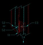
Post #1520: you ask about the compression ratio (SD/S2) for the model in Post #1518, it is about 2.3 (522/240). I'll attach a sketch of the box construction I was trying to model. I think Hornresp does not allow you to put the driver/throat at S1, so when you model an enclosure with no or minimal S1 and no or minimal distance between S1 and S2 you have to make some adjustment in the model and hope that the end result is still correct.
Under Le I added 2.5 to your Le of 0.89, I also took a wild guess at the inductors resistance as 0.20 in Rg. When you add a series inductor you have to still optimize the elements in Hornresp to arrive at a flat response (if you care). To me it's half the fun of having a wonderful tool like Hornresp as a design aid to keep on manipulating the parameters and seeing what I can come up with.
Post #1525, quote: "...the main problem I can see is that L34 needs to be 60cm, which is longer than the box. Does this mean I have to move the driver up inside the box?" - Yes, the enclosure design has to reflect the model. For the simples enclosure construction it would be helpful to reduce S3 to S4, but, there are a lot of ways to fold a tapped horn as the different subwoofer by Danley Sound Labs show. Take a look at Tom Danley's patent for an interesting folding method (Post #1147 by Marcello) that uses no S1 to S2 distance, a small throat and a longer S3 to S4 distance.
Hi MikeHunt79:
Post #1520: you ask about the compression ratio (SD/S2) for the model in Post #1518, it is about 2.3 (522/240). I'll attach a sketch of the box construction I was trying to model. I think Hornresp does not allow you to put the driver/throat at S1, so when you model an enclosure with no or minimal S1 and no or minimal distance between S1 and S2 you have to make some adjustment in the model and hope that the end result is still correct.
Under Le I added 2.5 to your Le of 0.89, I also took a wild guess at the inductors resistance as 0.20 in Rg. When you add a series inductor you have to still optimize the elements in Hornresp to arrive at a flat response (if you care). To me it's half the fun of having a wonderful tool like Hornresp as a design aid to keep on manipulating the parameters and seeing what I can come up with
.Post #1525, quote: "...the main problem I can see is that L34 needs to be 60cm, which is longer than the box. Does this mean I have to move the driver up inside the box?" - Yes, the enclosure design has to reflect the model. For the simples enclosure construction it would be helpful to reduce S3 to S4, but, there are a lot of ways to fold a tapped horn as the different subwoofer by Danley Sound Labs show. Take a look at Tom Danley's patent for an interesting folding method (Post #1147 by Marcello) that uses no S1 to S2 distance, a small throat and a longer S3 to S4 distance.
Attachments
This is as good as I could get for below 60Hz... It's not amazing, but it may be ok?
Volume = 125l
EDIT: Just seen your reply th46, exellent stuff. I also find I spend far too long in hornresp just changing the various parameters to see what happens, it's a great program.
I'll get reading about how to fold this thing, hopefully folding should solve more problems than it causes... It would be good to be able to access the driver thru the horn mouth tho, to save having a seperate access panel. I'll also have a look at the patents, I did have a quick skim a while ago and a lot of it went over my head, but hopefully I should understand it a bit better now.
One last question, is there a way of calculating or finding the best taper or angle for the horn path of L23?
An externally hosted image should be here but it was not working when we last tested it.
Volume = 125l
EDIT: Just seen your reply th46, exellent stuff. I also find I spend far too long in hornresp just changing the various parameters to see what happens, it's a great program.
I'll get reading about how to fold this thing, hopefully folding should solve more problems than it causes...
It would be good to be able to access the driver thru the horn mouth tho, to save having a seperate access panel. I'll also have a look at the patents, I did have a quick skim a while ago and a lot of it went over my head, but hopefully I should understand it a bit better now. One last question, is there a way of calculating or finding the best taper or angle for the horn path of L23?
I have not read all of this thread, so this may have been discussed, and discarded, but here goes.
<Half Baked Idea>
One of the problem that seems to be causing the most grief with the TH is the high freq ripple. Could part of the solution be to mate a bandpass with the throat of the horn?
My thought would be instead of firing the driver directly into the throat, have it fire into a chamber that is ported into the throat. This is sort of the idea of the Decware "Wicked One", but that doesn't use the back wave of the driver, ie it's a 4th order bandpass horn.
My reasoning is that bandpass enclosures have a tendency to sharply attenuate the high & low end of the spectrum, and it might act as a natural low pass filter.
</Half Baked Idea>
I can see a lot of obstacles trying to design such a beast, in that I can't imagine any off the shelf software being up to the task, and it adds a whole new set of variables to the equation.
Paul
Yes it is, you may get better results if you tweak a few values tho...aceinc said:Mike:
I assume that is based on my specs... If so thanks.
I look forward to your post on folding.
Paul
I need some sleep now, it's 4am in the UK, and I don't want to turn into an insomniac!
- Home
- Loudspeakers
- Subwoofers
- Collaborative Tapped horn project