G'day again Ian
>Your info about port nonlinearity is very interesting, and much more severe than I would have expected for decent-sized ports (20cm diameter per driver) -- how did you calculate these numbers? This is exactly the kind of large-signal effect that's ignored by most speaker modelling software (but obviously not yours")
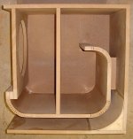
Tom is spot on bringing up the port non linearity problem. Most modelling software will not show you just how bad the problem is. I've attached a picture of one of a pair of subs I was using in a domestic environment a few years ago. My aim was to reduce this port nonlinearity as much as possible. 250L box volume with an Fb of 22Hz. The port took up over 100L of the box volume yet still had measurable port compression. The driver used was the 18 Sound 18LW1400. This is the cleanest high output vented sub I've built. It's performance can be beaten with a much cheaper driver in a tapped horn.
>But I have to point out that most people (amateurs like me!) don't use big stacked arrays, which is why I was comparing a single tapped horn with a dual 18" reflex -- 133dB at 1m from a 320l box is enough for the likes of me
A sub sitting in the corner is acoustically the same as a stack of four subs. I put mine in the corners. The tapped horns respond very well with this placement.
Cheers
William Cowan
>Your info about port nonlinearity is very interesting, and much more severe than I would have expected for decent-sized ports (20cm diameter per driver) -- how did you calculate these numbers? This is exactly the kind of large-signal effect that's ignored by most speaker modelling software (but obviously not yours
Tom is spot on bringing up the port non linearity problem. Most modelling software will not show you just how bad the problem is. I've attached a picture of one of a pair of subs I was using in a domestic environment a few years ago. My aim was to reduce this port nonlinearity as much as possible. 250L box volume with an Fb of 22Hz. The port took up over 100L of the box volume yet still had measurable port compression. The driver used was the 18 Sound 18LW1400. This is the cleanest high output vented sub I've built. It's performance can be beaten with a much cheaper driver in a tapped horn.
>But I have to point out that most people (amateurs like me!) don't use big stacked arrays, which is why I was comparing a single tapped horn with a dual 18" reflex -- 133dB at 1m from a 320l box is enough for the likes of me
A sub sitting in the corner is acoustically the same as a stack of four subs. I put mine in the corners. The tapped horns respond very well with this placement.
Cheers
William Cowan
Attachments
TH v. Bass Reflex
iand: Hi Ian, Thanks for the screenprints, that will give me something to look at. You may also try downloading the free Gadwin PrintScreen utility, it gives you additional capture features.
Actually, I feel that William Cowan and Tom Danley have already answered the question you posted, but, I'll see if I find anything useful to add (low probability).
djk: Thanks for helping with the screen capture.
cowanaudio: Post #1222: Now, that's a duct, nice woodworking.
cowanaudio said:G'day MaVo
Generally 3:1 is seen as the upper limit when designing bass horns. More than this puts too much stress on the cone, which will soon fail. This rule of thumb applies with pro sound drivers in a pro sound environment, but I believe is applicable at home too. I have seen photos of drivers that have been ripped up in horns with a too high compression ratio, so this is a very real problem. I think in comparison the distortion created when using high compression ratios is a non issue. In the home the levels where this will become significant will be causing plenty of distortion in the structure of the listening room!
Cheers
William Cowan
Hi William, i thought about this and searched in the lab forum archive for information. I found a post by Tom, concerning the throat distortion in the lab and bt7. First of all, just like you said, throat distortion in a basshorn seems to be no issue, even with such extreme designs as the bt7. the problem is the one you mentioned, that the driver can get torn up.
The strain on the driver and throat distortion is proportional to the driver velocity, which Tom pointed out in this post. The equation "velocity = excursion * frequency" describes the velocity. We see, that velocity rises with frequency and excursion.
One could take the labhorn as an example for what strain is acceptable. It seems to have a compression ratio of around 3 and can be used to around 100hz - judging from the response, maybe up to 200hz - but i dont know the exact numbers. With this information together with the fomula v=x*f we can get maximum compression values for horns with different xmax and cutoff. The cone stability has obviously a place in this equation, but i think one can assume that two high quality drivers with about the same cone weight will have about the same limit here.
For example, a horn with 50hz upper cutoff, which is about half of the labhorn and the same xmax as the lab could have a compression which is twice the labhorns compression. Another example which could accept the doubled compression could be, that we want the same upper cutoff of 100hz, but limit the excursion to the half, since we only want to use it in a home environment.
Following this, i would say, if we choose the right constrains, such as low cutoff or spl, we can build horns with compression ratios of greater than 3. I have simulated a TH with a peerless xxls 830842 with a compression factor of 6. The constrain could be to limit it to frequencies lower than 50hz. This design easily scales to lower cutoffs (i would really like to hear/feel a <20hz sine wave
) by adding horn length to each horn and increasing the number of horns.Attachments
G'day MaVo
I'm not sure that velocity is the right parameter to look at if you want to get a feel for the acoustic load on the driver. Consider a 10:1 compression ratio, the driver would have a very great load on it, but the excursion and therefore the velocity would be low. Picture two drivers mounted face to face and driven with the same polarity, so they are fighting each other. The load on the driver would be very great, but the excursion would be nearly zero. You would likely destroy the drivers if you pushed them very hard.
Also remember that the LAB12 driver was specifically designed for horn loading, and as such is very robust. It's likely a driver with a lower Mms will not be as robust as the LAB12.
Be careful.
William Cowan
cowanaudio said:G'day MaVo
I'm not sure that velocity is the right parameter to look at if you want to get a feel for the acoustic load on the driver. Consider a 10:1 compression ratio, the driver would have a very great load on it, but the excursion and therefore the velocity would be low. Picture two drivers mounted face to face and driven with the same polarity, so they are fighting each other. The load on the driver would be very great, but the excursion would be nearly zero. You would likely destroy the drivers if you pushed them very hard.
Also remember that the LAB12 driver was specifically designed for horn loading, and as such is very robust. It's likely a driver with a lower Mms will not be as robust as the LAB12.
Be careful.
William Cowan
Agreed completely.
You could imagine that the driver has to "lift"(move, etc) all of the air in the horn. That is a substantial amount of mass! I know thats not how it works exactly, but I think its a good analogy to consider.
Or maybe that it is essentially mechanically(using air) linking the mouth of the horn to the drivers cone. If the mouth has a huge surface area compared to the throat, then there will be a large amount of resistance to the cones movement.
Hmm...well at least thats how I view it.
Hi William, i think i assumed a constant horn load on the driver over all frequencies, so to speak an ideal horn with a flat frequency response. As the horn unloads the driver in the low frequencies and becomes acoustically invisible, the strain will be even lower.
Lets say we have this perfect horn and a 10:1 compression ratio. Imagine you push the cone to its xmax limit with your hand and hold it there. This will not strain the driver. Now imagine making the compression ratio higher to maybe 50:1 and and doing the same. Nothing will strain the driver, as long as you push it slowly enough. This is a simulation of a near dc signal. With such a big compression ration, imagine pushing the cone in and out periodically. The strain might increase a little, which you could feel as a force, which opposes your pushing, as the frequency rises.
Here we have an example were one can see that the force on the driver rises with frequency, excursion and compression ratio. One could make a pseudo equation like "strain = excursion * frequency * compression ratio". Because frequency * excursion = velocity, we can write "strain = velocity * compression ratio". Now lets take the drivers construction into account. My assumption has to be that the drivers robustness is proportional to its cone mass. Then you can write "strain = velocity * compression ratio / mass".
Your example of two same polarity drivers works very well with my pseudo equation. The compression ratio for such an example would be very high, thus you have to keep the other factors (excursion and frequency) low, to prevent damage. If you have very robust drivers, you could increase velocity a little, as it can stand more strain.
Hi judtoff, please imagine, that the driver has to lift all the air in the horn very slowly. This will be no problem. Imagine, it has to do this very fast, which will be a problem. Imagin you build a heavier cone, now it can stand a heavier load. This is were i take my pseudo equation from.
If it helps.
The dynamic mass of the air load must increase as the horn becomes more efficient.
Look at a couple of examples.
reflex efficiency ~2% implying that 98% of the input is converted to heat in the VC and cables.
Horn efficiency ~50% implying the same heat conversion in the VC but all of the remainder of the input is converted via the horn air load into acoustic output.
Would it be right to assume that the horn air load is 50/2 (100-50%/100-98%) more massy than the reflex?
Good question AndrewT. I hope someone with a little more knowledge can help us here, as all i do is guesswork.
My approach was simply to take a very efficient horn like the labsub and take its parameters as a limiter for other designs, since i think that Tom has made it as efficient as possible, leaving little room for improvement. Then i tried to find a relation how i could transfer this limit into other designs. This is where the equation comes from, which i posted earlier.
My reasoning is this: If the lab12 in a labhorn can take the strain of 13mm excursion at 100hz, then it could (if the xmax would be bigger) also accept a 26mm excursion of 50hz, which would equate into the same amount of stress on its structure. For example, if the labhorn would be limted to 50hz upper cutoff, it could accept a doubled compression ratio.
I dont know it this is correct, but i doubt that a rule of thump (for example a maximum of 3,5 ratio for basshorns) is accurate under all circumstances, especially since what we do here is not really PA woofer realm. I think that in reality one can trade different factors, which i would like to identify. In the moment, i think the factors are frequency, excursion, compression factor and cone stability. You and William mentioned the air load on the driver, generated due to the efficiency of the horn. I dont know how to take this into the equation.
Pressure/Force
A few ideas floating around the topic of maximum compression ratio.
The cone can fail when the unbalanced force on it becomes too large.
Two scenarios come to mind:
a) pistonic: when the limit is the strength of the weakest ring of the cone (probably fails around an arc then tears outwards (seems quite common from pictures of cone fractures)
b) modal: when an air mode (or at higher frequency a cone mode) leads to too-great shear about a nodal line (probably less common, requiring an "error" in design - but I can think of one or two ways it could be accentuated).
AkAbak can tell us the overall force (or equivalently pressure) on the cone. That should be good enough to hint at potential problems. A few (not very systematic) tests show that, in slightly different THs and looking around 30-50 Hz, the force can vary drammatically for very little change in the efficiency.
I'm not sure where to expect failure, but >>100N forces starts to get a bit scary, I guess.
That - with some experience and trusting AkAbak- should cover a). Probably b) is a relatively minor problem except in a particularly poor design (unless I'm missing some obvious case).
If I had an AkAbak Lab-sub model I'd make some comparisons, but I don't - I agree that is a good reference point.
Ken
cowanaudio said:G'day MaVo
I'm not sure that velocity is the right parameter to look at if you want to get a feel for the acoustic load on the driver. Consider a 10:1 compression ratio, the driver would have a very great load on it, but the excursion and therefore the velocity would be low. Picture two drivers mounted face to face and driven with the same polarity, so they are fighting each other. The load on the driver would be very great, but the excursion would be nearly zero. You would likely destroy the drivers if you pushed them very hard.
Also remember that the LAB12 driver was specifically designed for horn loading, and as such is very robust. It's likely a driver with a lower Mms will not be as robust as the LAB12.
Be careful.
William Cowan
If you drive a ported box at resonance the cone barely moves at all, which is equivalent to a horn with a very high compression ratio. Also there's then no cooling from air being pumped past the coil (which all high-power drivers rely on), which is exactly how I cooked the coil on my McCauley 6174 -- both ends of coil fried, middle OK where it was being cooled by the gap and top plate :-(
There's lots of stuff being talked over the years about drivers failing in horns with high compression ratios, and funnily enough these have always been drivers (usually large diameter) with fairly weak cones. I've never heard of any reported cone failure for drivers with very strong cones (LAB12, Ciare 12.00SW etc.) even when operated at high CR.
It's nothing directly to do with being in a horn as such, it's just that the coil pushes on the cone via the coil former and air pressure pushes back via the cone area such as to keep the coil still, but the two forces aren't in line so if the cone's too weak it will give way.
This can happen in exactly the same way in a horn, a reflex (at box resonance), a bandpass (at either box resonance) or an extremely small closed box.
Ian
cowanaudio said:G'day again Ian
>Your info about port nonlinearity is very interesting, and much more severe than I would have expected for decent-sized ports (20cm diameter per driver) -- how did you calculate these numbers? This is exactly the kind of large-signal effect that's ignored by most speaker modelling software (but obviously not yours
Tom is spot on bringing up the port non linearity problem. Most modelling software will not show you just how bad the problem is. I've attached a picture of one of a pair of subs I was using in a domestic environment a few years ago. My aim was to reduce this port nonlinearity as much as possible. 250L box volume with an Fb of 22Hz. The port took up over 100L of the box volume yet still had measurable port compression. The driver used was the 18 Sound 18LW1400. This is the cleanest high output vented sub I've built. It's performance can be beaten with a much cheaper driver in a tapped horn.
>But I have to point out that most people (amateurs like me!) don't use big stacked arrays, which is why I was comparing a single tapped horn with a dual 18" reflex -- 133dB at 1m from a 320l box is enough for the likes of me
A sub sitting in the corner is acoustically the same as a stack of four subs. I put mine in the corners. The tapped horns respond very well with this placement.
Cheers
William Cowan
Hi William
What was the predicted port velocity in your 250l/22Hz (actually 150l + 100l port) box, and was the port flared? There's some disagreement about the allowable port velocity for low distortion/compression, the box I proposed peaks at just over 20m/s which is below most recommendations, but may still have some compression as Tom said -- I'd still like to know how he calculated those figures
I'm not surprised you could beat the 18LW1400 in a 150l 22Hz reflex with a tapped horn, it's parameters are *way* off the optimum for a box with this size and tuning (Xmax is *far* too low, Sd is too high). The Seismic 8196 I've got in a 450l 25Hz box right now is rather closer to optimum but still some way off.
The BMS18N850V2 in a 140l 32Hz box (or a pair of these) is very close to the best that is theoretically possible in a reflex (just the right balance of BL/Mmd/Xmax to be thermally and Xmax limited at 1200W) -- which is why I'm asking if *this* can be beaten by a tapped horn, not something which is nowhere near optimum.
Of course any sub will have higher output against a wall or in a corner, not just a tapped horn. But this isn't a choice you always have when playing with a band, the PA has to go where the venue allows...
Ian
Hi kstrain, I didnt think of akabak at all, so i need to investigate this. If akabak can model (a), then all my previous thoughts are rendered useless in a good way. I think (b) is not important in a TH, since we are way out of the area of cone resonances.
A model of a Labhorn wouldnt be too complicated to script. Do you have a link handy, which shows the internal diameters as a function of distance from throat? If not, i could try to calculate them from the prosoundweb labhorn documentation. Other subs could use the data as a reality check then.
A model of a Labhorn wouldnt be too complicated to script. Do you have a link handy, which shows the internal diameters as a function of distance from throat? If not, i could try to calculate them from the prosoundweb labhorn documentation. Other subs could use the data as a reality check then.
Re: Pressure/Force
You don't need any complicated modelling or mathematics -- we're not operating in the mass loaded region here so the force applied to the cone by the coil through the former is just BL*I, and if the cone's not moving (or not much) due to the enclosure (whatever type) this must be balanced by pressure*area.
With 1200W/8ohms nominal drive level at the impedance minimum (resonance) the current would be something like 22A peak, which with BL=25N/A means a peak driving force force of about 55kg at the coil former, with a similar counterbalancing force spread over the whole area of the cone.
With big drivers (18") with thin cones it's hardly surprising that they rip themselves to pieces. With smaller (12") drivers with very strong cones (LAB12, Ciare12.00SW) this should be OK -- a 4" coil on a 10" cone only has 3" of cone offset outside the coil.
Ian
kstrain said:A few ideas floating around the topic of maximum compression ratio.
The cone can fail when the unbalanced force on it becomes too large.
Two scenarios come to mind:
a) pistonic: when the limit is the strength of the weakest ring of the cone (probably fails around an arc then tears outwards (seems quite common from pictures of cone fractures)
b) modal: when an air mode (or at higher frequency a cone mode) leads to too-great shear about a nodal line (probably less common, requiring an "error" in design - but I can think of one or two ways it could be accentuated).
AkAbak can tell us the overall force (or equivalently pressure) on the cone. That should be good enough to hint at potential problems. A few (not very systematic) tests show that, in slightly different THs and looking around 30-50 Hz, the force can vary drammatically for very little change in the efficiency.
I'm not sure where to expect failure, but >>100N forces starts to get a bit scary, I guess.
That - with some experience and trusting AkAbak- should cover a). Probably b) is a relatively minor problem except in a particularly poor design (unless I'm missing some obvious case).
If I had an AkAbak Lab-sub model I'd make some comparisons, but I don't - I agree that is a good reference point.
Ken
You don't need any complicated modelling or mathematics -- we're not operating in the mass loaded region here so the force applied to the cone by the coil through the former is just BL*I, and if the cone's not moving (or not much) due to the enclosure (whatever type) this must be balanced by pressure*area.
With 1200W/8ohms nominal drive level at the impedance minimum (resonance) the current would be something like 22A peak, which with BL=25N/A means a peak driving force force of about 55kg at the coil former, with a similar counterbalancing force spread over the whole area of the cone.
With big drivers (18") with thin cones it's hardly surprising that they rip themselves to pieces. With smaller (12") drivers with very strong cones (LAB12, Ciare12.00SW) this should be OK -- a 4" coil on a 10" cone only has 3" of cone offset outside the coil.
Ian
Re: Re: Pressure/Force
In most well damped TH models I've got (I'm working on a 20 to 60 Hz design) the two force peaks are just a bit below the corresponding zero crossings of the phase of the impedance (e.g. 18Hz and 52 Hz in one case). If I was worried about this I think I'd be more concerned about the upper peak with most music, although the peak force for a given input is just over half of the lower peak.
Since I was in any case using AkAbak (as well as Hornresp) the force calculation came free.
I'd not looked at the force very seriously (just giving it a glance from time to time) until reading this thread this weekend (I'm not going to play music loudly enough in my room to rip a cone even with "high compression", even if I actually get round to finishing a TH eventually) .
Ken
iand said:
You don't need any complicated modelling or mathematics <snip>.
Ian
In most well damped TH models I've got (I'm working on a 20 to 60 Hz design) the two force peaks are just a bit below the corresponding zero crossings of the phase of the impedance (e.g. 18Hz and 52 Hz in one case). If I was worried about this I think I'd be more concerned about the upper peak with most music, although the peak force for a given input is just over half of the lower peak.
Since I was in any case using AkAbak (as well as Hornresp) the force calculation came free.
I'd not looked at the force very seriously (just giving it a glance from time to time) until reading this thread this weekend (I'm not going to play music loudly enough in my room to rip a cone even with "high compression", even if I actually get round to finishing a TH eventually) .
Ken
G'day again Ian
>What was the predicted port velocity in your 250l/22Hz (actually 150l + 100l port) box, and was the port flared?
It had a Vb of 250L, not 150L. The volume occupied by the port must always be taken into consideration, especially when the port is this large. The port had a huge flare on both ends, it was a 100 or 150mm radius, from memory (see the picture posted above). Predicted port velocity was ~30M/S at 800W.
>Of course any sub will have higher output against a wall or in a corner, not just a tapped horn. But this isn't a choice you always have when playing with a band, the PA has to go where the venue allows...
Horns have more to gain in a corner than ported boxes. I thought we were talking domestic environments here?
Cheers
William Cowan
cowanaudio said:G'day again Ian
>What was the predicted port velocity in your 250l/22Hz (actually 150l + 100l port) box, and was the port flared?
It had a Vb of 250L, not 150L. The volume occupied by the port must always be taken into consideration, especially when the port is this large. The port had a huge flare on both ends, it was a 100 or 150mm radius, from memory (see the picture posted above). Predicted port velocity was ~30M/S at 800W.
>Of course any sub will have higher output against a wall or in a corner, not just a tapped horn. But this isn't a choice you always have when playing with a band, the PA has to go where the venue allows...
Horns have more to gain in a corner than ported boxes. I thought we were talking domestic environments here?
Cheers
William Cowan
Hi William
I'm not surprised you saw significant compression at 30m/s -- but I do agree it's not easy to make ports big enough to avoid this issue, certainly many designs have far too little port area.
I never said I was talking domestic environments -- I'd have to be completely insane to be playing a 5-string bass at home with 2400watts per channel. Or maybe you don't have neighbours in Australia? (or shelves that things fall off)
As Tom said, horns do gain more efficiency from mutual coupling that direct radiators, either with multiple boxes or reduced radiation angle.
But the tapped horn is effectively being promoted as "the bass horn that works with a single box in half-space, not an array" and "more output than any other single box of its size" -- it's these claims that I'm challenging.
Not because I don't believe Tom, or think the tapped horn isn't a clever solution to an old problem -- but because, try as I might, I haven't been able to design one that beats the good old double 18" reflex with any driver I've tried, even by tweaking parameters. But maybe somebody else (Tom?) can...
So that's the challenge, design a tapped horn that beats this:
320l total net volume, -3dB at 33Hz, flat from 40-100Hz or above
133dB maximum output (half-space, no power compression)
(without exceeding mathematical Xmax = (Hc-Hg)/2 + Hg/4)
99dB/W, 2400W power handling into nominal impedance
Of course higher efficiency and lower power handling is fine so long as maximum output level is the same (without exceeding Xmax anywhere in the passband)
I'll allow designs that can't sustain 133dB continuously, this could be pretty tough for a single-driver tapped horn and isn't needed for music anyway -- though it does help with power compression.
If the tapped horn needs a driver that doesn't exist but could be built that's fine -- but no 8" drivers with +/-3" Xmax, please
OK, that's your homework for today.
Cheers
Ian
Hi all, i modeled a quick labhorn, took the data from this page:
http://www.geocities.com/hulkss/LABsub3.html
(used the labv2 data, which is like the original, as the guy says.)
Script is this:
Def_Driver 'Lab12'
Sd=507cm2
fs=22.1Hz
Qes=0.39
Qms=13.32
Vas=125L
Re=4.29ohm
Le=1.48mH
system 'S1'
Driver 'd1' Def='Lab12' Node=1=0=10=12
Driver 'd2' Def='Lab12' Node=1=0=11=12
Enclosure 'E1' Node=10 Vb=17L
Enclosure 'E2' Node=11 Vb=17L
Waveguide 'H1' Node=12=13 STh=540cm2 SMo=700cm2 Vf=20.6L Len=20cm Conical
Waveguide 'H2' Node=13=14 STh=700cm2 SMo=769cm2 Len=30cm T=1
Waveguide 'H3' Node=14=15 STh=769cm2 SMo=2580cm2 Len=150cm T=1
Horn 'H4' Node=15=16 STh=2580cm2 SMo=5800cm2 Len=79cm T=1
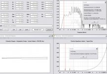
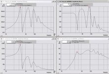
Results are attached. Now i only need to gain the knowledge on how to interprete them correctly, and maybe i should make a simulation with full excursion, but i was too lazy right now.
http://www.geocities.com/hulkss/LABsub3.html
(used the labv2 data, which is like the original, as the guy says.)
Script is this:
Def_Driver 'Lab12'
Sd=507cm2
fs=22.1Hz
Qes=0.39
Qms=13.32
Vas=125L
Re=4.29ohm
Le=1.48mH
system 'S1'
Driver 'd1' Def='Lab12' Node=1=0=10=12
Driver 'd2' Def='Lab12' Node=1=0=11=12
Enclosure 'E1' Node=10 Vb=17L
Enclosure 'E2' Node=11 Vb=17L
Waveguide 'H1' Node=12=13 STh=540cm2 SMo=700cm2 Vf=20.6L Len=20cm Conical
Waveguide 'H2' Node=13=14 STh=700cm2 SMo=769cm2 Len=30cm T=1
Waveguide 'H3' Node=14=15 STh=769cm2 SMo=2580cm2 Len=150cm T=1
Horn 'H4' Node=15=16 STh=2580cm2 SMo=5800cm2 Len=79cm T=1
Results are attached. Now i only need to gain the knowledge on how to interprete them correctly, and maybe i should make a simulation with full excursion, but i was too lazy right now.
Attachments
G'day again Ian
I can't match the target you presented in a vented box model, not even neglecting to take into account thermal compression (which is very real at the power levels you propose) or any compression in the port. The BMS 18N850 drivers are not up to the task anyway.
Cheers
William Cowan
I can't match the target you presented in a vented box model, not even neglecting to take into account thermal compression (which is very real at the power levels you propose) or any compression in the port. The BMS 18N850 drivers are not up to the task anyway.
Cheers
William Cowan
- Home
- Loudspeakers
- Subwoofers
- Collaborative Tapped horn project