Re: Sims
Greets!
OK, using my interpretation of ML's math and pipe horn design, I get a bit different gain BW/larger 377.394L with your axial length. Regardless, there's nothing wrong with your design if you plan to XO it down around 70 Hz, though many folks have worse dips in their rooms than this TH and don't mind it, so you may can XO it much higher if you prefer. Only one way to know for sure.
Note that since it's a 15" driver the minimum distance to the throat and mouth is 19.21 cm, not 15 cm and you need to put at least 0.1 ohms of series resistance in the 'Rg' field since it affects the sim. Also, PE's measured specs are somewhat different to the published ones, so I recommend trying them in your design before cutting any wood.
WRT finding power required to reach Xmax, either double click on the 'Eg' field to input watts/nominal load and re-calculate to see how it affects excursion or just input a voltage to see what it takes to reach Xmax at whatever cut-off frequency you choose, then calc watts required: W = E^2/R
With my sim it takes 20 V/100 W to reach the 10 mm Xmax at ~16 Hz, so with your lower tuning, though smaller TH, it's probably about the same.
GM
Attachments
Re: Sims
GM,
I thought I read somewhere that the big dip around 60-70hz was a desired characteristic of TH? That this dip made it easier to XO? Your sim has the response looking more flat--is this more desired? I recall somewhere in this thread that a more sloping response would be desirable in a home setting. Should I make my results look more like yours and just EQ and be happy with the added headroom?
Hi,
I have finally made it through this thread and cannot help but wonder if somebody has done some work on trying to tame the response with Helmholz resonators similar to the design example by E. Jakulis on a TQWT (tapered quarter wave tube)?
It seems that a similar technique would be almost necessary to optimize this design.
tb46 said:Hi,
I have finally made it through this thread and cannot help but wonder if somebody has done some work on trying to tame the response with Helmholz resonators similar to the design example by E. Jakulis on a TQWT (tapered quarter wave tube)?
It seems that a similar technique would be almost necessary to optimize this design.
Wouldn't that be more trouble than it's worth?
Hoffman's law tells us that high efficiency designs are always bandwidth limited, or require a huge box. In a lot of ways a tapped horn is like a dual reflex bandpass, albeit easier to build and tame.
Re: Re: Sims
Greets!
News to me, but if the two octave BW below it is all you need, then sounds like a good plan to me.
Yeah, I think I posted that since most rooms have some gain down low, but folks keep touting 'flat', so just going with the 'flow' WRT sims. In this respect, yours will probably perform better overall in-room than mine and it has enough headroom to EQ and still meet DD/DTS reference, not to mention it's the smaller of the two.
GM
tb46 said:
It seems that a similar technique would be almost necessary to optimize this design.
Greets!
You can go through all that trouble if you want, I prefer to use a little stuffing if need be and let the XO deal with the rest of it., plus I gather that the 'ripple' isn't as bad as predicted. Anyway, if you make it big enough it all gets smoothed out enough.
GM
tb46 said:Hi,
I have finally made it through this thread and cannot help but wonder if somebody has done some work on trying to tame the response with Helmholz resonators similar to the design example by E. Jakulis on a TQWT (tapered quarter wave tube)?
It seems that a similar technique would be almost necessary to optimize this design.
I believe this is one of the techniques that Tom Danley uses on his DTS 20. Perhaps he can 'pipe up' (hee hee) and give us feedback on how it's used and if it's worth it.
Well, I mentioned a few posts ago a combination of a helmholtz resonator and compression chambers on both sides of the driver to make a tapped horn more "bandpass". So this resonator would help as a lowpass filter around the desired upper cutoff.
After briefly discussing these ideas to one of the "Powers That Be"") , he said I should give it a shot in AkAbak to see if there were any merits. Unfortunately by having to work again and not being proficient in AkAbak, I asked for help as my efforts stranded, but I still haven't got a reply.
, he said I should give it a shot in AkAbak to see if there were any merits. Unfortunately by having to work again and not being proficient in AkAbak, I asked for help as my efforts stranded, but I still haven't got a reply.
Either he is too busy or quite possibly this was a silent hint to throw it in the group and let everybody help and benefit.
Anyway, here is the script I threw together:
---------------------------------------------------------
Def_Driver 'SPH-212'
dD=21,2cm dD1=6,5cm tD1=2,5cm |Cone
fs=30Hz Vas=82L
Qms=2,21 Qes=0,5 Re=6,2ohm fre=8kHz Le=0.6mH
System 'RLDCTH'
Driver Def='SPH-212' Node=0=1=2
Duct 'Resonator' | 80Hz one end closed resonator
Node=0=3
sD=0,15m2
Len=100cm
Radiator 'AfterResonator' Def='Resonator'
Node=3=0
x=0 y=0 z=0 HAngle=0 VAngle=0
Duct 'FrontCompchamber'
Node=2=3
sD=0,15m2 Len=1cm Vf=20L
Radiator 'AfterFrontCChamber' Def='FrontCompchamber'
Node=3=0
x=0 y=0 z=0 HAngle=0 VAngle=0
Waveguide 'Conical Horn'
Node=1=2
STh=0,218m2 SMo=0,44m2
Len=350cm Conical
Horn 'Endhorn'
Node=2=0
STh=0,44m2 SMo=1m2
Len=60cm T=1
x=0 y=0 z=0 HAngle=0 VAngle=0
--------------------------------------------------------------
This is an effort for a group of different elements I tried to put into one system:
- the front of the driver loads a compression chamber to act as a lowpass.
- this compression chamber exits in a straight single ended 1/4 WL resonator tube for negative interference at the desired High cutoff.
- the open end of the resonator loads the throat.
- the back of the driver also loads a compression chamber for the same reasons as the front.
- this back compression chamber loads the mouth of the horn.
As you'll see from the SPL plot, it seems the resonator part works, but I have my doubts if I have the rest of the nodes correct, i.e. if the back chamber loads the mouth. Maybe someone else can clean this up? I'll much appreciate it.
It is interesting but not suprising - héhé - that Tom Danley seems to use the same ideas. I didn't know that.
Some more toughts about this:
- by tuning the front and back chambers I think it can be possible to adjust the apparent T/S parameters of the driver to better suit the TH. For example make the suspension more stiffer by higher compression ratios?
- Hornresp testing indicates the throat area should be fairly large with this particular driver, so maybe the front chamber should be omitted?
- the back chamber loads the lower frequencies into the TH, so there higher compression ratio's (and thus more filtering of the higher frequencies) can be beneficial and possibly reduce reflections into the horn?
- what will be the effect on the size of the TH? the more high freq you want to filter, the larger chambers you need so you get a larger TH ...
- will it actually work to divert the energy from the high freq for more output in the desired low freq passband?
Any toughts about this is much appreciated and I hope the above script in all its raw-ness is of *some* use to anyone ...
Joris
After briefly discussing these ideas to one of the "Powers That Be"
, he said I should give it a shot in AkAbak to see if there were any merits. Unfortunately by having to work again and not being proficient in AkAbak, I asked for help as my efforts stranded, but I still haven't got a reply.Either he is too busy or quite possibly this was a silent hint to throw it in the group and let everybody help and benefit.
Anyway, here is the script I threw together:
---------------------------------------------------------
Def_Driver 'SPH-212'
dD=21,2cm dD1=6,5cm tD1=2,5cm |Cone
fs=30Hz Vas=82L
Qms=2,21 Qes=0,5 Re=6,2ohm fre=8kHz Le=0.6mH
System 'RLDCTH'
Driver Def='SPH-212' Node=0=1=2
Duct 'Resonator' | 80Hz one end closed resonator
Node=0=3
sD=0,15m2
Len=100cm
Radiator 'AfterResonator' Def='Resonator'
Node=3=0
x=0 y=0 z=0 HAngle=0 VAngle=0
Duct 'FrontCompchamber'
Node=2=3
sD=0,15m2 Len=1cm Vf=20L
Radiator 'AfterFrontCChamber' Def='FrontCompchamber'
Node=3=0
x=0 y=0 z=0 HAngle=0 VAngle=0
Waveguide 'Conical Horn'
Node=1=2
STh=0,218m2 SMo=0,44m2
Len=350cm Conical
Horn 'Endhorn'
Node=2=0
STh=0,44m2 SMo=1m2
Len=60cm T=1
x=0 y=0 z=0 HAngle=0 VAngle=0
--------------------------------------------------------------
This is an effort for a group of different elements I tried to put into one system:
- the front of the driver loads a compression chamber to act as a lowpass.
- this compression chamber exits in a straight single ended 1/4 WL resonator tube for negative interference at the desired High cutoff.
- the open end of the resonator loads the throat.
- the back of the driver also loads a compression chamber for the same reasons as the front.
- this back compression chamber loads the mouth of the horn.
As you'll see from the SPL plot, it seems the resonator part works, but I have my doubts if I have the rest of the nodes correct, i.e. if the back chamber loads the mouth. Maybe someone else can clean this up? I'll much appreciate it.
It is interesting but not suprising - héhé - that Tom Danley seems to use the same ideas. I didn't know that.
Some more toughts about this:
- by tuning the front and back chambers I think it can be possible to adjust the apparent T/S parameters of the driver to better suit the TH. For example make the suspension more stiffer by higher compression ratios?
- Hornresp testing indicates the throat area should be fairly large with this particular driver, so maybe the front chamber should be omitted?
- the back chamber loads the lower frequencies into the TH, so there higher compression ratio's (and thus more filtering of the higher frequencies) can be beneficial and possibly reduce reflections into the horn?
- what will be the effect on the size of the TH? the more high freq you want to filter, the larger chambers you need so you get a larger TH ...
- will it actually work to divert the energy from the high freq for more output in the desired low freq passband?
Any toughts about this is much appreciated and I hope the above script in all its raw-ness
is of *some* use to anyone ... Joris
Hi again,
GM: I hope you are right and the response irregularities are not as bad as they look in Hornresp; I just doubt that a cross-over can eliminate the kind of spiking that is apparent in most of the SPL graphs. I agree, a little stuffing, or maybe lining of the horn path would probably help.
MartinQ: I think you are right. As you said it sure would be nice if Tom Danley could shine some light on this aspect of the subject. I cannot believe that all that nice volume from the speaker front to the bottom of the DTS-20 is just throat extension.
Cordraconis: That sounds like an interesting design approach, might get structurally a little complex; resonators seem easier to implement. But, a really interesting AkAbak application.
Thanks for all the advice and information.
tb46: That sounds like an interesting design approach, might get structurally a little complex; resonators seem easier to implement. But, a really interesting AkAbak application.
Upon closer inspection I just noticed I forgot a comp chamber for the rear end of the driver. I'll give it a shot tomorrow.
The structural complexity might not be that bad after all: if my guess is correct that a front comp chamber can be left out, then only a back one would be nessesairly and if the motor assembly can extend into the resonator at the throat, then this back chamber can be as little as the space under the cone when the driver is screwed over a 1/2 sD hole near the mouth.
The resonator and the front chamber could be built into one but I first want to sim the effect of 2 separate ones first. So first I need to get the script working.
You speak of multiple resonators, but how would you implement that? I also considered several res at the throat, but since they all fire into the same throat wouldn't this couple all of them together into one resonant system as opposed to multiple separate ones?
The same could be true to some extent for my res+dual chambers idea, but I think this might be a bit different since comp chambers are not real helmholtz resonators and I see them more as acoustic compliance modificators.
that's it for today, off to work!
And the next one, plus the link:
http://baseportal.de/cgi-bin/basepo...io/download&cmd=list&range=0,20&cmd=all&Id=13
http://baseportal.de/cgi-bin/basepo...io/download&cmd=list&range=0,20&cmd=all&Id=13
Attachments
ah, now I get it. Thanks for the JPG's. I'll have a look at the paper later.
So far I've put the back compression chamber and a corner loading reflector into the script but there isn't much approvement in the SPL plot.
The driver diaphragm displacement from akabak shows a gently sloping curve starting from 400hz till a whopping 2m (!) at 20Hz, which makes me think the driver isn't coupled to the system at all.
However, in the excursion dialog I can see the nodes and the connected components of the system so I'll try to use that to determine where the problems with my script are.
Clearly the learning curve of AkAbak takes longer than about 4 hours of educated cut-and-pasting-and-adjusting from the Help files.
You might check in AkAbak that your 1 meter isn't actually 1mm. I just got into it, as well, to model tapped horns that hornresp wont. I was amazed to find displacement of 1 meter as well, especially at just .7 volts in, but if you double click the dark grey box that says(in my case)
"Uin=0.7Vrms"
"--TappedHor, N=2=3, Driver (diaph) 1"
It'll bring up a "Diagram Edit Range" Dialog, and you can see the vertical limits of the graph. My guess is that in your case it will tell you that the upper limit is 1 or 2cm and that the "1m" at the graph's edge stands for 1milli-.
On the subject of AkaBak, can anyone tell me if there is a way to get .5pi or 1pi predictions?
Joseph Decker
To add reflection (for 1/8th, ... 1/4th ... space ...) you have to define a reflector and put in the keyword reflection at the end horn or the last radiator. See my latest script below.
Getting a good sleep after 4 days finally paid off: I think I figured out the node-system of AkAbak and here is the result. This script looks more like I think it should behave.
-----------------------------------------------------------
Def_Reflector TopCorner
Left=1.0m Top=1.0m Right=1.0m
HAngle=45.0°
Def_Driver 'SPH-212'
dD=21,2cm dD1=6,5cm tD1=2,5cm |Cone
fs=30Hz Vas=82L
Qms=2,21 Qes=0,5 Re=6,2ohm fre=8kHz Le=0.6mH
System 'RLDCTH'
Driver Def='SPH-212'
Node=1=0=200=300 |Driver connected to node 200 and 300
Duct 'FrontCompchamber'
Node=200=201 |driven by node 200 (front driver) and it drives/connects to node 201 (open end of resonator)
sD=0,110m2 Len=1cm Vf=20L
Radiator 'AfterFrontCChamber' Def='FrontCompchamber'
Node=201
x=0 y=0 z=0 HAngle=0 VAngle=0
Duct 'Resonator' |80Hz one end closed resonator
Node=0=201 |def "resonator" with node 0 as closed end and connected to node 202
sD=0,110m2
Len=100cm
Waveguide 'Conical Horn'
Node=201=301 |Conical horn between nodes 201 and 301
STh=0,200m2 SMo=0,300m2
Len=350cm Conical
Duct 'BackCompchamber'
Node=300=301 |Driven by back of driver and drives/exits in the conical horn
sD=0,110m2 Len=1cm Vf=20L
Radiator 'AfterBackCompChamber' Def='BackCompchamber'
Node=301
x=0 y=0 z=0 HAngle=0 VAngle=0
Horn 'Endhorn'
Node=301 |Horn driven by node 301 (conical horn+output back comp chamber)
STh=0,300m2 SMo=0,500m2
Len=60cm T=1
x=0 y=0 z=0 HAngle=0 VAngle=0 dEdge=3m Reflection
-----------------------------------------------------------------
The Unity horn script MaVo posted some months ago, was most helpfull to give me the insight.
Now I have to do a direct comparison between HornResp and my script to see if they are similar.
Once again: if someone sees faults or errors in the above script, *please* point them out. Thanks in advance.
Recent Sims
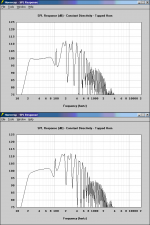
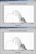
Here are some sims I have beenplaying around with. I have some for the Dayton Quatro 8".
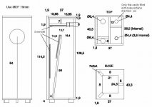
Dayton Quatro 8" in TH ranging in volume from 100 - 150L. Is there any preference for hometheater? I have 2 more sims to come of the same driver. The sims are in order of smallest volume to largest.
Here are some sims I have beenplaying around with. I have some for the Dayton Quatro 8".
Dayton Quatro 8" in TH ranging in volume from 100 - 150L. Is there any preference for hometheater? I have 2 more sims to come of the same driver. The sims are in order of smallest volume to largest.
Attachments
Tang Band Comments
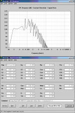
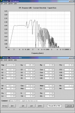
I tried changing the Qes from .3 to .4 on the 8" subwoofer and in the sims using Hornresp it starts looking pretty good. Would it be possible to adjust the Ques by varying the amplifier impedance as stated in this article:
http://sound.westhost.com/articles/cscaling.htm
If so then this driver may look something like this in a 117L TH:
Attachments
- Home
- Loudspeakers
- Subwoofers
- Collaborative Tapped horn project