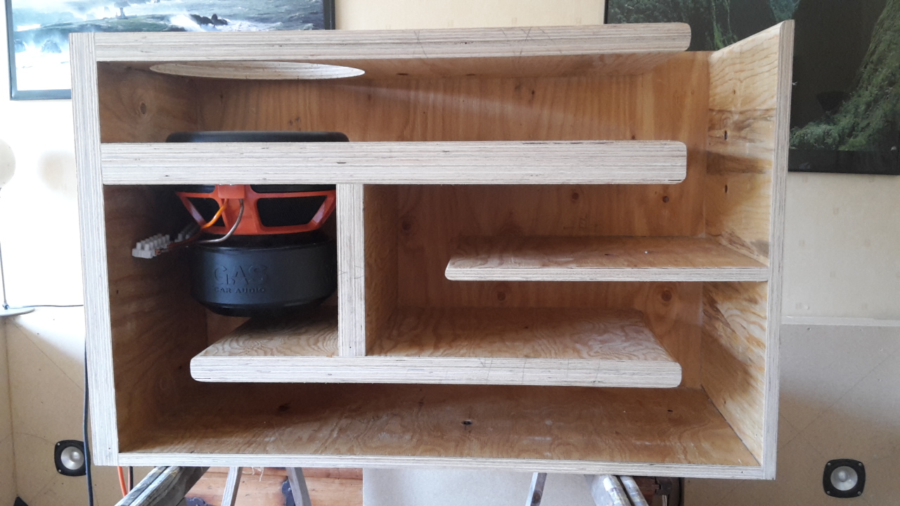
This is only a dry-mount of the parts. My son built that box last year.
It was built with a Alpine SWR8D2, so this box is a lot smaller then the simulation I posted previous in this thread.
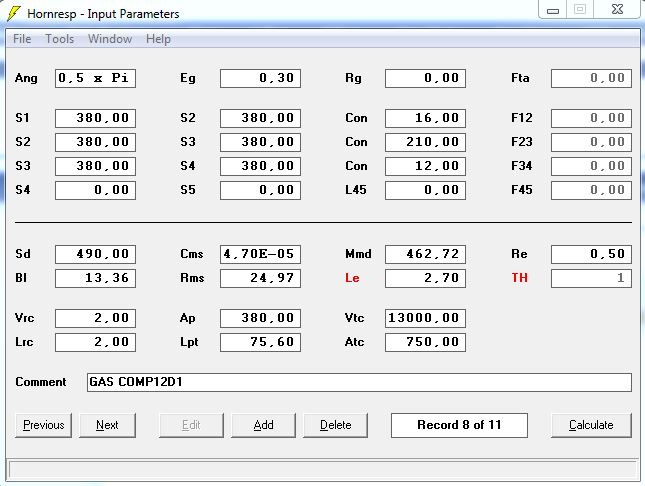
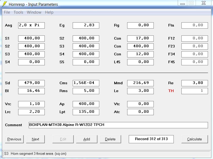
TPCH with an Alpine SWR8D2
Oh, the input screen says 12" sub.
It is a CH feeding a large front resonator. It gets quite large, but I do like the efficiency and large bandwidth.
I consider this to be a tapped horn, since both CH resonators couple together in the large front resonator, but I would agree that this might start to push the boundaries of the definition of a "tapped horn".
CH = parallel port BP6 = 2 exits.
TH = series port BP6 = 1 exit.
Or add a much needed third piece of plywood to the baffle.
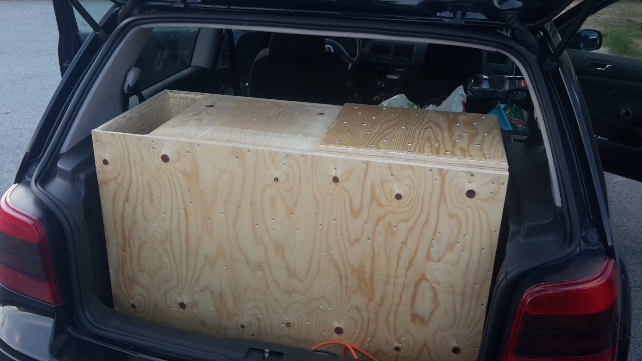
Here is another build we did last summer:
This was built to play loud in a car. 144 dB with 3500 watts at 29 Hz is quite uncomfortable...
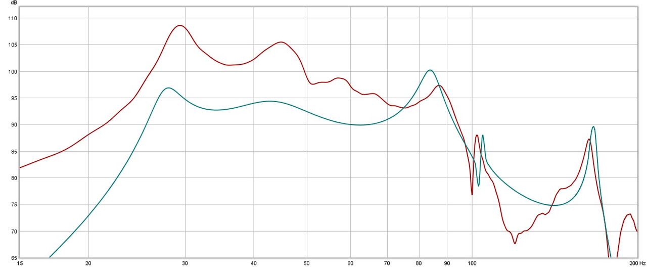
Measurement in the car vs simulation.
That transfer function kicked in nice from 75hz on down!
Was the simulation 2 or 0.5pi?
If 2pi, then you should have measured the enclosure outside the car to see if the model is correct.


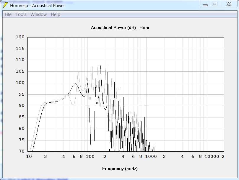
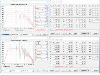
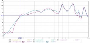
I found some more pictures and measurements of the TPCH with the Alpine 8 inch driver on my old laptop.
The last picture of the build showing the driver and double layer plywood baffle, measured (outdoors with microphone 30 cm from the mouth) and simulated spl and group delay.
If you add a front pipe section to a simple tapped pipe you can get a much larger usable passband. You get the same distortion nulling effect as Brian Steel mentions above.
Here compared with your "baseline" simulation above.
Dear Circlomanen,
Many thanks for your design suggestion, the modelled response looks great.
Would you be able to provide me with a sketch of the enclosure please?
I am yet to understand how to translate the Hornresp into a real enclosure.
Regards
Those 10dB peaks outside of the passband are going to amplify any distortion produced by the build, but the FR looks pretty decent.
For comparison purposes, here's the sim'd response of an offset TL using the same driver (semi-inductance not enabled). SPL level is about 2dB lower, but usable passband is wider and the box is also half the size. And there are no 10dB out-of-band peaks to worry about.
Hi Brian,
I think I'm going to to have to build this box!
How would I take what is in this image and reverse engineer the enclosure using your Boxplan-MLTL workbook please?
Thanks
MLTL and some stuffing
Hi Brian,
I managed to recreate your nice MLTL sim with a little stuffing.....
But now my next question is .....
Thanks.
Hi Brian,
I managed to recreate your nice MLTL sim with a little stuffing.....
But now my next question is .....
Thanks.
Attachments
Lab12 with a Alpine R-W12D2 Tapped Horn
So I wanted to report back after my previous posts and all the help I received that I went ahead and built the Snider Lab12 and got great results with an old Alpine SWS-1242 and the new Alpine R-W12D2.
This design sounds great!

So I wanted to report back after my previous posts and all the help I received that I went ahead and built the Snider Lab12 and got great results with an old Alpine SWS-1242 and the new Alpine R-W12D2.
This design sounds great!
Attachments
Last edited:
Longtime reader, first time designer
Hi everyone,
I've been following these threads and playing with hornresp and other tools occasionally for a few years now with the intent of building myself a sizeable horn sub. I've got 5 sheets of 3/4" plywood just waiting to be cut up for this.
I've been throwing inexpensive drivers into hornresp and playing around, and finally think I found something I'd like to further develop, so I'm looking for some more experienced input on my tinkering. I haven't started working out the folding yet, but I think I've sized things so I can fit it within a 4'x8' sheet for top & bottom and leave 3 to cut up for the internals.
Here's my current Horn resp parameters

.png")
This is the latest driver I've tried and it's cheap enough that I considered doing 2 in series, as shown.
Any advice or recommendations for this design? Have I over-focused on something and missed an important consideration?
I've noticed the last few years that whatever I do, my Phase Response has always looked terrible. Do I need to re-think something to fix that?

Thanks.
Hi everyone,
I've been following these threads and playing with hornresp and other tools occasionally for a few years now with the intent of building myself a sizeable horn sub. I've got 5 sheets of 3/4" plywood just waiting to be cut up for this.
I've been throwing inexpensive drivers into hornresp and playing around, and finally think I found something I'd like to further develop, so I'm looking for some more experienced input on my tinkering. I haven't started working out the folding yet, but I think I've sized things so I can fit it within a 4'x8' sheet for top & bottom and leave 3 to cut up for the internals.
Here's my current Horn resp parameters
This is the latest driver I've tried and it's cheap enough that I considered doing 2 in series, as shown.
Any advice or recommendations for this design? Have I over-focused on something and missed an important consideration?
I've noticed the last few years that whatever I do, my Phase Response has always looked terrible. Do I need to re-think something to fix that?
Thanks.
So I wanted to report back after my previous posts and all the help I received.......This design sounds great!

GM
Hi everyone.........I'm looking for some more experienced input on my tinkering..........I've noticed the last few years that whatever I do, my Phase Response has always looked terrible.
It's the 'nature of the beast' due to being increasingly out of phase above the tap point, but you'll be XOing it above 60-80 Hz/4th or higher order, so it all goes away.
As for the design, it fine overall considering it's for a weak motor tuned well below Fs, so 'rings' quite a bit due to its huge net Vb relative to its Vas.
Personally prefer to design based on a single driver for best overall power handling vs box size, then add a second one to further preload it, so to speak now that inexpensive comprehensive DSP is available to optimize its in room response.
Load mine and overlay to yours at its 240 W rated power to see that once both are low/hi passed, yours will only have a little more rolled off sub bass unless using a higher power amp/EQ to boost its big dips and hope the driver can handle it [doubtful if it distorts as bad as the cheap JBL, Kenwood, weird named ones my neighbor's kids use in their vehicles].
GM
Attachments
Thanks for the thoughts GM. I think I can see what you're describing.
I had looked as it as a single driver before going to the 2-series, but I adjusted the horn segment cross sections after changing to series to get the response curve back to that mostly flattened version. Sounds like maybe I shouldn't do that and just accept that I can electronically compensate.
Maybe I should reconsider that particular driver choice. There were a couple other 12s that I had put through hornresp recently, definitely a couple that had stronger motors and more Xmax.
You're welcome!
Well, I did have to make the first section 2x bigger or the doubled [4:1] compression ratio would have destroyed the driver at high power, which flattened out the taper ratio out the terminus [mouth].
Right, 'no replacement for displacement' when high output is desired/required.
GM
Well, I did have to make the first section 2x bigger or the doubled [4:1] compression ratio would have destroyed the driver at high power, which flattened out the taper ratio out the terminus [mouth].
Right, 'no replacement for displacement' when high output is desired/required.
GM
@JLH, AllenB mentioned yesterday your tapped horn with dual 8PE21 in another thread. Sadly, the pictures in this thread are long gone. Is there any chance you may have these and post them again? Originally, they were here: https://www.diyaudio.com/community/...apped-horn-project.97674/page-89#post-1505236. I was experimenting a bit with Hornresp and tapped horns and I actually came up with a single fold TH for Fane Sovereign 8-225, but I also have a pair of 8PE21s (the 8-ohm version). Seeing that you did this a long time ago and with very nice results, I would really appreciate any inspiration for my project. Thanks!
- Home
- Loudspeakers
- Subwoofers
- Collaborative Tapped horn project