Re: Re: TD*H
Note that this applies at both ends, so both sims have a too short L34.
GM
MaVo said:
Try a value of half the driver diameter as a starting point. This way, you can simply put the driver at the end of the horn, without having to build a front chamber.
Note that this applies at both ends, so both sims have a too short L34.
GM
littlemike_quad W6-1139
Hi littlemike,
Just looked at the construction (Post #2996) and the Hornresp Input Parameters for your Quad cabinet again, and I wonder if the compression (coupling?) chamber is not acting more as an extension of the horn, rather than as a separate chamber. The horn flare is basically just extended through the chamber, and the block defining the chamber port area will probably just appear as a restriction in the horn. This may explain why the enclosure tests a little longer than the model.
Regards,
Admittedly - it is not much of a "port" so you may be on to something there. The compression chamber would add about 40 cm to the horn length. For easy math, simply split that value in half, so L12 would be 20 cm and L23 would increase by 20 cm. I do not have the model stored on this PC, so I can not check now, but I will see if that may be the case.
Anyhow, now I need to make it look a bit nicer, adjust the bass boost/subsonic filter in the amp (BASH 500) to a value appropriate for this enclosure, mount the amplifier, and deliver it to its new home. Weather and time permitting, I'll get 1W/1M groundplane SPL measurements too, though I've got to calibrate my SPL meter to a known reference first.
Anyhow, now I need to make it look a bit nicer, adjust the bass boost/subsonic filter in the amp (BASH 500) to a value appropriate for this enclosure, mount the amplifier, and deliver it to its new home. Weather and time permitting, I'll get 1W/1M groundplane SPL measurements too, though I've got to calibrate my SPL meter to a known reference first.
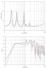
So - I re-ran the model with 20 cm added to L12 and L23 and the chamber removed as discussed earlier. Impedance matched up a little better in the upper peaks, but the low peak is definitely lower. Predicted magnitude is still higher than measured though. This is likely an effect of the batting I used in the throats.
Spl is not terribly different - the major curve features match up a little better with what I measured up to about 200 Hz. The 120 Hz spike is still prevalent in the model, but I simply did not see it with the SPL meter, if anything I have a bit of a null just over 100 HZ. This may be a measurement artifact, I'll see if it is still there when I run some groundplane sweeps outside.
New comparison plots are attached. New modeled data is in red, black is the original model, and the blue is what I measured.
Also played a bit more music through it and sort of placed it in a corner as a test. What a difference! This thing is frightening when corner loaded. Hard to believe I am listening to 4 6-inch drivers.
Got the BASH amp subsonic filter modified tonight too. Replaced the stock filter with a maximally flat curve with an fc of 30 Hz. I chose to leave a little on the table so to speak to save the woofers from excessive excursion. The amp even works afterwards, BONUS! I borrowed a nice SPL meter so that I could adjust my meters to a known standard. As it turns out, I was only off a couple of dB, which is a lot better than I thought. Now that everything is set, I'm probably within a dB or two of reality - which is plenty good for what I am trying to do.
Quick question - when measuring the 1W/1M response curve, which frequency is the 1W measured at? I know that watts = volts * amps, and I know that amps will vary based on the impedance of the load per Ohm's Law. After that I get a bit confused. Seems to me that I have a variable impedance and 2.83 V at 20 or 40 Hz will be less watts (higher impedance) than 2.83 V applied at 30 Hz (lowest impedance). I was thinking I'd measure at 60 Hz, as it is a pretty flat spot in the impedance curve and my meter is most accurate at 60 Hz. Technically, with a 5 ohm load - I think I need about 2.24 volts for one watt of power.
What is the most meaningful way to do this? Numbers that no one else can use are not really worth gathering or presenting.
That's probably enough for tonight.
Attachments
Hi,
set the test voltage to a fixed standard.
Use the same voltage for all frequencies.
2.83Vac into 8r0=1W.
That's as good a standard as any for a sensitivity measurement and for a frequency response.
There was a standard, but I rarely see it now, of using a test voltage that gave 96dB of SPL and plot distortion with frequency at that volume.
measuring speaker sensitivity
Hi littlemike,
Maybe this link to a "stereophile magazine" article will help:
http://www.stereophile.com/reference/99/index2.html
But, above all, keep on measuring, that is good data you are providing. Thanks
Regards,
Hi littlemike,
Maybe this link to a "stereophile magazine" article will help:
http://www.stereophile.com/reference/99/index2.html
But, above all, keep on measuring, that is good data you are providing. Thanks
Regards,
Interesting data ")
This could be an internal 1/2 WL standing wave. For example: For a standing wave to exist at 100hz you need to have a path of 1,72m length. For example between the bottom and top walls in the box. This would repeat the notch at N*1/2 WL, (200,300,400hz and so on).
littlemike said:The 120 Hz spike is still prevalent in the model, but I simply did not see it with the SPL meter, if anything I have a bit of a null just over 100 HZ. This may be a measurement artifact, I'll see if it is still there when I run some groundplane sweeps outside.
This could be an internal 1/2 WL standing wave. For example: For a standing wave to exist at 100hz you need to have a path of 1,72m length. For example between the bottom and top walls in the box. This would repeat the notch at N*1/2 WL, (200,300,400hz and so on).
On the subject of simulated response vs real response:
We have observed, that in reality, peaks in the response have a smaller q and and less size than in the simulations. Also, Tom said once, that the simulations assume a too high q. In the real world, we have losses, which make peaks and notches q smaller, making response more even. I would say, this is a good thing.
Now, why do we brace the boxes then? By bracing them, we make the losses smaller. Its just like in room acoustics, if you have walls that can bend, the room is less resonant, has smaller and broader peaks. If you look at Toms tapped horns, he even adds damping material, which should add to the same effect. Intuitively i would have said, you have to brace your tapped horns, but the thought above would say the opposite.
So, what do you think?
MaVo said:
Now, why do we brace the boxes then? By bracing them, we make the losses smaller. Its just like in room acoustics, if you have walls that can bend, the room is less resonant, has smaller and broader peaks. If you look at Toms tapped horns, he even adds damping material, which should add to the same effect. Intuitively i would have said, you have to brace your tapped horns, but the thought above would say the opposite.
So, what do you think?
I think the bracing is for the pass-band...
Even made of 3/4" & doubled up 1/2" (1") inside baffles of baltic birch, and extensively braced, if played @ near live spls, if I put my hand on the side wall, there's a fair amount of vibration...
I'm thinking I should double the outside panels now, or even go to a spaced layer & fill w/ sand.
That vibrating speaker cabinet has to be adding its own distortion...
Agreed, GM. Here is a related post from the lab archive, for some added perspective: http://www.live-audio.com/messages/archive3/52112.html
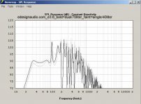
This driver a good Tapped Horn candidate?
http://www.edesignaudio.com/product_info.php?t=2&products_id=33
http://www.edesignaudio.com/product_info.php?t=2&products_id=33
Just glancing at the specs, I'd guess that driver would want to be in a 15 hz tapped horn, but the horn would be so small the driver probably wouldn't fit inside, so you'd have to use multiple drivers to get csa large enough and to get usable spl. If you do that you might as well just start with a bigger driver.
So I'd have to say no unless you want to make several extremely small but very low tuned tapped horns or some type of very compromised design.
So I'd have to say no unless you want to make several extremely small but very low tuned tapped horns or some type of very compromised design.
Posts #3014 - #3015_e3.6 Subwoofer
Hi Kevin,
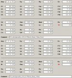
I used the parameters from the website, and entered them into the Hornresp input screen. The values Hornresp ends up calculating and the manufacturer's data do (as is often the case) not completely agree. For a real design you need the measured driver parameters.
Regards,
Hi Kevin,
I used the parameters from the website, and entered them into the Hornresp input screen. The values Hornresp ends up calculating and the manufacturer's data do (as is often the case) not completely agree. For a real design you need the measured driver parameters.
Regards,
Attachments
Here is the 2.83V 1M 2pi response.
My mic was adjusted to measure within 0.5 dB of a known calibrated mic, but still - take these measurements with a grain of salt.
I measured ~92 dB at 2.83V, Hornresp predicts ~95. I'm 3 dB down from predicted. This could be a result of measurement techniques, could be batting. Weather was not good for outdoor measurements - we had fairly strong winds. The enclosure still easily reaches the SPL needed in room without any excursion issues.
More importantly - it is fairly flat where I hoped it would be - it is within 3 dB of 91 dB from 30 Hz to 150Hz - long past the upper crossover point.
Anyhow - here it is - as a PDF.
Attachments
Thanks again, this is all good stuff. You didn't happen to do 28.3V at 10m did you? That seems to be danley's method, just wondering what the difference might be.
3db down is expected I would think due to stuffing and possibly measurement location - for example a concrete surface will probably be a bit (maybe a lot) louder than on grass, so a lot depends on the rigidity of the 2pi boundary condition I would guess. I wouldn't lose any sleep wondering where that 3db went.
Congrats on the first ever wide bandwidth diy tapped horn. (Unless I missed one somewhere)
I am pretty sure that William Cowan designed, built, and tested a tapped horn with a much wider passband than I achieved here long before I built this one. This design was definitely a compromise, as it was primarily designed to fit the space available. Once it fit the space I had to work with, I worked on the design to make 30-100 Hz response work as well as possible. Fortunately the measured response of what I built is even flatter than the predicted response in Hornresp. These drivers will definitely play louder/lower in an enclosure with less design compromises.
It got set up in its new home over the weekend. The in room response rises by 4 dB across the passband as frequency drops, it definitely excites a room node at 20 Hz, and there is a fairly large null at 120 Hz which is outside the range I am really concerned with. We tried several positions, but the null was fairly persistent. With an 80 Hz crossover, it blended nicely with the main speakers. A bit of delay helped de-localize the bass somewhat. The sub amplifier gain is set pretty low - approximately 25%, but the sub still outruns the rest of the system. A quick RTA check indicated that the response of the entire system was a little bass-heavy, but otherwise flat. Dropping the gain on the sub amp a touch more should even things out.
Listening to it is a lot of fun. There is plenty of headroom for music's dynamics, and it plays quite low. The impact is surprising. It is still amazing to me that 4 little 6-inch drivers in a DIY enclosure perform this well. I've not heard back on home theater performance yet, but if it is anything like the music we listened to, it should be great.
Did not do the 28.3V/10M measurement for three reasons:
The weather was not cooperating.
I do not have a 100W non-inductive resistor (yet).
My neighbors must live closer to me than Danley's do. While no one complained or called the sheriff, I definitely got their attention while testing and playing around with the sub.
The weather was not cooperating.
I do not have a 100W non-inductive resistor (yet).
My neighbors must live closer to me than Danley's do. While no one complained or called the sheriff, I definitely got their attention while testing and playing around with the sub.
- Home
- Loudspeakers
- Subwoofers
- Collaborative Tapped horn project