rhapsodee said:Am i doing something wrong with the parameters?
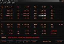
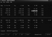
Hornresp->Tools->Driver Arrangement->Tapped Horn->OK
MaVo said:
Lower the crossover point and use one with a higher order. What you hear are the high frequencies, bouncing around in the horn.
Ditto, I realised that the TH-112 is definitely not happy with a 2nd order xover even with a sharp BW-12, unless its crazy low (and then it won't gel with my Lambda TD15M-A). Its BW-24 varying between 80-90Hz now with some EQ to rid the peaks @ LP.
No felt or damping in my TH-112 though.
Guys, my TH-112 uses a slightly modified LAB12 (but still 13mm Xmax probably), the cab is ~ 300L and I think some of you know the folding.
Do you think that Xmax is reached at 30Hz with 800W?
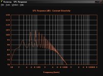
Here's some clues with the FR graph (28V 10m). Its 101dB @38 and drops to 95dB @ 30.
Thanks!
Do you think that Xmax is reached at 30Hz with 800W?
Here's some clues with the FR graph (28V 10m). Its 101dB @38 and drops to 95dB @ 30.
Thanks!
Hi,
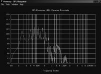
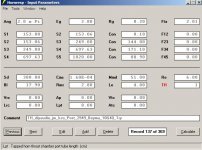
I have corrected the mistakes pointed out earlier, now seem to have a response that looks relatively like a tapped horn.
I'm concerned about the large 10dB dip at 40 Hz, as Tom Barker found out when he built his tapped horn that the dip did not fully fill out.
Comments and feedback appreciated!
http://www.lsdm.co.uk/doggspace/tappedhorns.html
Attachments
Is tapped horn for me ?
Hi Tapped Horn gurus,
for this project, I will soon start investigating the bass element.
I have difficulties measuring how low my mains go (will go) but measures seems the show the go down to 100Hz and I think the go a bit below.
The use has shifted a bit, it was pure HT but is now back to 50% hifi/50% HT... I like the sound of the mains too much to use them only for HT") .
.
I will need to cover from 100/80Hz down to 30Hz. I know I could target lower, but I am not too keen on having to deal with room modes and so on (if I understood correctly, they can be nasty below 30Hz).
I have not settled with a technology yet (I mean sub technology, sealed, veted, BP, TH), but I have been following the various TH threads with interest. As I am working on my mains, I have a Beyma 10G40 lying around doing nothing.
I got hooked by the extended response (is it unique to TH though ?) and (mostly ) by the "bass for money" ratio as TH seems to achieve the kind of output usually devoted to $$$ large speakers.
Playing a bit with HR, it could look like this in a 4m TH.
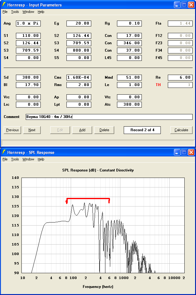
Question 1 : do you think it is worth the wood and time to give it a try or the curve is too uggly ? The driver might be a bit too luxurious for TH, but it is the one I have available for test.
Question 2 : Any chance to get rid of the spikes in the "red area". I tried changing various sizes at length, but the best I can achieve is compromising the rest of the response. I see some have added coils, is it the way to go ? (I assume it either change drive parameters or just act as a low pass filter).
Question 3 : I currently have no DCX or Reckhorn or thing of the sort, just an HT amp (and 2/3 old hifi stereo spare amps), how can I try this with my limited hardware ?
And I have to say I am a real noob, but willing to learn.
[EDIT] The simulation is for 20w where the driver seem to reach Xmax...
[EDIT 2] I used spec sheet parameters...
Hi Tapped Horn gurus,
for this project, I will soon start investigating the bass element.
I have difficulties measuring how low my mains go (will go) but measures seems the show the go down to 100Hz and I think the go a bit below.
The use has shifted a bit, it was pure HT but is now back to 50% hifi/50% HT... I like the sound of the mains too much to use them only for HT
.I will need to cover from 100/80Hz down to 30Hz. I know I could target lower, but I am not too keen on having to deal with room modes and so on (if I understood correctly, they can be nasty below 30Hz).
I have not settled with a technology yet (I mean sub technology, sealed, veted, BP, TH), but I have been following the various TH threads with interest. As I am working on my mains, I have a Beyma 10G40 lying around doing nothing.
I got hooked by the extended response (is it unique to TH though ?) and (mostly
) by the "bass for money" ratio as TH seems to achieve the kind of output usually devoted to $$$ large speakers.Playing a bit with HR, it could look like this in a 4m TH.
Question 1 : do you think it is worth the wood and time to give it a try or the curve is too uggly ? The driver might be a bit too luxurious for TH, but it is the one I have available for test.
Question 2 : Any chance to get rid of the spikes in the "red area". I tried changing various sizes at length, but the best I can achieve is compromising the rest of the response. I see some have added coils, is it the way to go ? (I assume it either change drive parameters or just act as a low pass filter).
Question 3 : I currently have no DCX or Reckhorn or thing of the sort, just an HT amp (and 2/3 old hifi stereo spare amps), how can I try this with my limited hardware ?
And I have to say I am a real noob, but willing to learn
.[EDIT] The simulation is for 20w where the driver seem to reach Xmax...
[EDIT 2] I used spec sheet parameters...
raphsodee Post #2948
Hi raphsodee,
For what its worth: check the T/S parameters in your input data, there are disagreements between the factory data, the data you entered, and the data Hornresp calculates. Ideally you should measure the data for the unit you are using, otherwise you are just guessing.
Regards,
Hi raphsodee,
For what its worth: check the T/S parameters in your input data, there are disagreements between the factory data, the data you entered, and the data Hornresp calculates. Ideally you should measure the data for the unit you are using, otherwise you are just guessing.
Regards,
Attachments
Re: raphsodee Post #2948
Which of the parameters are you refering to? Hmm, just occured to me, i have the VCs in series, how does that affect the various parameters? BL doubles? How about Qes? I used the parameters from the attached spec sheet.
Do you mind posting the input parameters you used? Measuring the driver would be a bit tricky, as i don't really have the appropriate equipment.
Thanks!
tb46 said:Hi raphsodee,
For what its worth: check the T/S parameters in your input data, there are disagreements between the factory data, the data you entered, and the data Hornresp calculates. Ideally you should measure the data for the unit you are using, otherwise you are just guessing.
Regards,
Which of the parameters are you refering to? Hmm, just occured to me, i have the VCs in series, how does that affect the various parameters? BL doubles? How about Qes? I used the parameters from the attached spec sheet.
Do you mind posting the input parameters you used? Measuring the driver would be a bit tricky, as i don't really have the appropriate equipment.
Thanks!
Attachments
rhapsodee Post #2951
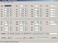
Hi rhapsodee,
I entered Sd, Re and Le and let Hornresp calculate Cms, and the other data points (using factory Vas, Q's...). There is a disagreement between the manufacturers data and the data Hornresp calculates, and if I have to make a choice I go with David McBeans calculations, as manufacturers data is often questionable.
The only point I wanted to make is, that you have to measure the T/S parameters for the driver you are using.
Regards,
Attachments
rhapsodee, the only way to get rid of the spikes in the simulation is to make the horn bigger, by making hornmouth bigger and adding more drivers or making Ang smaller by moving the sub in a corner. This rises the lower response part, while keeping the peaks at the same level. Out of hornresp, you can add damping material in the sub, but this cant be simulated accurately and is guess/measure work.
Re: Is tapped horn for me ?
Sorry for the repetition, but this is just in case my post got lost in the volume....
Many thanks for your answers/advices.
jm_kzo said:Hi Tapped Horn gurus,
for this project, I will soon start investigating the bass element.
I have difficulties measuring how low my mains go (will go) but measures seems the show the go down to 100Hz and I think the go a bit below.
The use has shifted a bit, it was pure HT but is now back to 50% hifi/50% HT... I like the sound of the mains too much to use them only for HT
I will need to cover from 100/80Hz down to 30Hz. I know I could target lower, but I am not too keen on having to deal with room modes and so on (if I understood correctly, they can be nasty below 30Hz).
I have not settled with a technology yet (I mean sub technology, sealed, veted, BP, TH), but I have been following the various TH threads with interest. As I am working on my mains, I have a Beyma 10G40 lying around doing nothing.
I got hooked by the extended response (is it unique to TH though ?) and (mostly
Playing a bit with HR, it could look like this in a 4m TH.
Question 1 : do you think it is worth the wood and time to give it a try or the curve is too uggly ? The driver might be a bit too luxurious for TH, but it is the one I have available for test.
Question 2 : Any chance to get rid of the spikes in the "red area". I tried changing various sizes at length, but the best I can achieve is compromising the rest of the response. I see some have added coils, is it the way to go ? (I assume it either change drive parameters or just act as a low pass filter).
Question 3 : I currently have no DCX or Reckhorn or thing of the sort, just an HT amp (and 2/3 old hifi stereo spare amps), how can I try this with my limited hardware ?
And I have to say I am a real noob, but willing to learn
[EDIT] The simulation is for 20w where the driver seem to reach Xmax...
[EDIT 2] I used spec sheet parameters...
Sorry for the repetition, but this is just in case my post got lost in the volume...
.Many thanks for your answers/advices.
MaVo said:rhapsodee, the only way to get rid of the spikes in the simulation is to make the horn bigger, by making hornmouth bigger and adding more drivers or making Ang smaller by moving the sub in a corner. This rises the lower response part, while keeping the peaks at the same level. Out of hornresp, you can add damping material in the sub, but this cant be simulated accurately and is guess/measure work.
Are you prescribing the above to fix the 35Hz dip between the first two peaks at about 25 Hz and 50Hz? My understanding is that the 'tap' in the tapped horn should fill this in somewhat and result in a relatively flat (before room gain) response?
Taking room gain into account, should we instead design for the lower peak (25Hz) to be about 6dB lower that the upper 50Hz peak?
I'm also quite concerned about the peaks between 80 to 150Hz, they are 6dB stronger than the 'bass' response of 25Hz to 60Hz. Will they be lower in the actual tapped horn? I'm guessing the damping material will help to reduce these frequencies, and also even out the peaks.
Post #2949
Hi Jean-Michel,Post #2949:
Neat "project: http://www.diyaudio.com/forums/showthread.php?s=&threadid=122996&perpage=25&pagenumber=3"
As to your simulation and questions:
Question 1: Use some inexpensive wood like particle board or OSB and keep one side removable to be able to make internal modifications. I would keep S1 larger than Sd/3. You only need a value for Atc if you are using a chamber between the driver and the horn, and I assume you added Rg for speaker wire.
Question 2: If you keep the distance L12 between 0.1cm and the driver cone radius, the upper end cleans up a bit, but, those peaks in the red region are there to keep. You can attenuate them by using 1/4 wave resonators of appropriate length for the peak center frequency, and by adding lining to the enclosure. Both of those fixes require measurements and experimentation. The effect of a series inductor can be simulated by adding its resistance in Rg and its inductance in Le. It is being said, that the peaks are not as strong in real life as in the simulation.
Question 3: Yes, you can obviously still add filtering, but to learn about building a tapped horn I recommend reading this thread (and taking notes), simulating in Hornresp (you are already doing fine there), measuring the T/S parameters of your driver, and definitely building an experimental box.
Regards,
Attachments
rhapsodee said:
I'm also quite concerned about the peaks between 80 to 150Hz, they are 6dB stronger than the 'bass' response of 25Hz to 60Hz. Will they be lower in the actual tapped horn? I'm guessing the damping material will help to reduce these frequencies, and also even out the peaks.
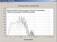
As William Cowan pointed out recently, the higher peaks are damped a bit by the box. Pics courtesty of WC's website.
Stuffing (or lining) will further reduce those higher peaks. This is an excellent study by WC, except for the fact that I can't correlate the claimed hornresp inputs for this horn, shown below (also courtesy of WC's site). For some reason, if I input these exact numbers into hornresp I get completely different results. So either he attached the wrong inputs or I'm just stupid. But other than that it's an excellent example.
- Home
- Loudspeakers
- Subwoofers
- Collaborative Tapped horn project