just a guy, the length of the resonators is easy. It's 1/4 of a wavelength of the peak you want to remove. Unstuffed and it will have a very high Q, but be a bit harder to tune to length, stuffed and the Q will be a little lower and the notch will be broader and slightly lower in frequency. Vary the stuffing with the aid of measurements. Unstuffed is probably the most correct solution. For example a 100Hz peak would be tamed with an 850mm resonator. Start off with some 65-90mm dia PCV pipe capped at one end and the open end of the line entering the horn very near the driver at the throat end. Smaller pipe (50mm) could be used for a very small (8") tapped horn. You can target several peaks with several different length WL/4 stubs.
There is a difference in the measured V's predicted response of these Tapped Horns, especially in the out of band top end. Most of the main features are there, but their Q and amplitude are generally lower. The real Tapped Horns are more lossy than the model predicts, so the modeled peaks are lower in amplitude and a little broader. Tom increases the losses in his boxes with the use of acoustic foam lining on the walls. This is probably used most of the way down the line. My measurements have shown it is a useful trick to smooth out the response in the top end. The foam has very little effect down low.
Careful driver selection is also very useful when aiming for maximum bandwidth. Some drivers just do much better. Try the 18 Sound 15LW1401 in a 30 Hz tapped horn. Corner loaded or in a block of four this combination can be flat to well over 200Hz. The 15TBX100 used in the TH115 is a similar driver and will give very good response without the need to resort to WL/4 resonators and other tricks.
I can't stress enough the need to measure a promising looking design. Then tweak it to tame the top end. Too many people are spending huge amounts of time running models, but not actually building these horns. I built/adjusted about 20 versions of the 30Hz Tapped Horn, without the ability to run quick simulations. Now that simulation is much easier we should all use this as a go/no go guide, but you've got to build and measure.
Cheers
William Cowan
Thanks so much for all that.
I'll try modelling the drivers you mentioned. If you can get 2.5 octaves just by choosing the right driver then I'm clearly using the wrong driver for extended bandwidth and I probably shouldn't bother even trying to extend it.
The drivers I am designing for are currently in customs, but I will definitely be building something and I measure everything now that I can.
So it's pretty clear now that a Volvotreter style of small tapped horn (or maybe 6th order bandpass) is the wisest choice. I'll just tune it so the big dip is right in the middle of my lowest room mode.
Thanks again Mr Cowan.
I'll try modelling the drivers you mentioned. If you can get 2.5 octaves just by choosing the right driver then I'm clearly using the wrong driver for extended bandwidth and I probably shouldn't bother even trying to extend it.
I can't stress enough the need to measure a promising looking design. Then tweak it to tame the top end. Too many people are spending huge amounts of time running models, but not actually building these horns. I built/adjusted about 20 versions of the 30Hz Tapped Horn, without the ability to run quick simulations. Now that simulation is much easier we should all use this as a go/no go guide, but you've got to build and measure.
The drivers I am designing for are currently in customs, but I will definitely be building something and I measure everything now that I can.
So it's pretty clear now that a Volvotreter style of small tapped horn (or maybe 6th order bandpass) is the wisest choice. I'll just tune it so the big dip is right in the middle of my lowest room mode.
Thanks again Mr Cowan.
In an attempt to find my own answers to some of my questions I started reading the thread again and found a couple of references to a very high mouth/throat ratio.
In post 694 WC suggests trying a design using a 7:1 ratio. (But then suggest even 5:1 may be too much.)
Post 169 in this thread http://www.diyaudio.com/forums/showthread.php?s=&threadid=79102&perpage=25&highlight=&pagenumber=7 shows what appears to be an early incarnation of the dts-20, apparently from the patent. The throat clearly comes to a point, putting the mouth:throat ratio at ~infinity.
What does that prove? Not much really, the TH SPUD is a much newer design and the ratio on that one is dramatically smaller. So a very high ratio may not necessarily be desirable but it doesn't seem to hurt. At least it doesn't seem to hurt Danley.
And on the throat side tap position, both the spud and the dts-20 (and the 2 patent pics I've seen posted) clearly depict end loading. This makes sense, as end loading usually corresponds to maximum possible output.
Only 72 more pages to go (not including external links)...
G'day just a guy
There is nothing wrong or bad with a high throat to mouth ratio. It's the compression ratio or Sd to throat that you have to be careful with. If the compression ratio is too high, you will suffer mechanical driver failure if the box is pushed hard. Three to one is about the limit for a very stout driver, two to one would help a more average driver survive.
A large throat to mouth ratio makes the box bigger and increases output and smooths response.
Cheers
William Cowan
previous patent ?
hi all
could someone point out the difference of this patent to Danley's tapped horn patent ?
http://www.google.com/patents?id=0ocbAAAAEBAJ&dq=High+efficiency+low+frequency+speaker+system
Angelo
hi all
could someone point out the difference of this patent to Danley's tapped horn patent ?
http://www.google.com/patents?id=0ocbAAAAEBAJ&dq=High+efficiency+low+frequency+speaker+system
Angelo
There is nothing wrong or bad with a high throat to mouth ratio. It's the compression ratio or Sd to throat that you have to be careful with.
Thanks again sir. Although I'm fascinated with horns they are obviously not my area of expertise and I seem to be getting confused a bit, particularly when the word "compression" comes up. (That's twice now)
JLH's model that we've been discussing seems to have a very high ratio of cone area: throat, it looks much higher than 3:1 and by all accounts he's not shy with the volume knob. Maybe smaller drivers are more rugged (strength goes down as cone area goes up)? Or maybe the tang bands just have strong little cones regardless of their size?
just a guy said:
particularly when the word "compression" comes up. (That's twice now)
Its simply a narrowing of the throath before entering the line...the woofer sees an opening smaller than its own area or displacement(?)
Your tweeter compression drivers work that way too...a 2" diaphragm playing into a 1" troath...a few months ago I didnt know that either...seems we learn something each day
")
tinitus said:
Its simply a narrowing of the throath before entering the line...the woofer sees an opening smaller than its own area or displacement(?)
Your tweeter compression drivers work that way too...a 2" diaphragm playing into a 1" troath...a few months ago I didnt know that either...seems we learn something each day
The real throat you can't see right next to the diaphragm is much smaller still, usually at least 5:1 compression ratio or higher...
Ian
Hi,
How about this one
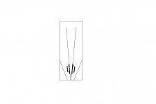
I would like to call it "Tapped-ACE", inspired from the famous quaterwave, the "ACE-horn"
Its simple, but I thought there wouldnt be much else to it, as the ordinary tapped design is even simpler
But now it got me thinking that I may have forgotten something about the original ACE-horn
The two internal lines are not completely alike as the "V" is offset a bit to one side
I am not sure excactly what it means, but could it be of any use fore a tapped-horn somehow
But I could imagine that it may be difficult to simulate
Any thoughts would be appreciated, thanks
edit, oh yes, maybe one driver should be turned the other way round, to make it push-pull, if thats significant
And maybe one driver should be mounted slightly higher, making it asymmetrick
It have been said that the push-pull needs a compression "chamber" to work properly, while others say that such design has its own flaws, and that driver should be able to breathe freely, resulting in less ripple, as I understand it
How about this one
I would like to call it "Tapped-ACE", inspired from the famous quaterwave, the "ACE-horn"
Its simple, but I thought there wouldnt be much else to it, as the ordinary tapped design is even simpler
But now it got me thinking that I may have forgotten something about the original ACE-horn
The two internal lines are not completely alike as the "V" is offset a bit to one side
I am not sure excactly what it means, but could it be of any use fore a tapped-horn somehow
But I could imagine that it may be difficult to simulate
Any thoughts would be appreciated, thanks
edit, oh yes, maybe one driver should be turned the other way round, to make it push-pull, if thats significant
And maybe one driver should be mounted slightly higher, making it asymmetrick
It have been said that the push-pull needs a compression "chamber" to work properly, while others say that such design has its own flaws, and that driver should be able to breathe freely, resulting in less ripple, as I understand it
Attachments
cowanaudio said:G'day just a guy
There is nothing wrong or bad with a high throat to mouth ratio. It's the compression ratio or Sd to throat that you have to be careful with. If the compression ratio is too high, you will suffer mechanical driver failure if the box is pushed hard. Three to one is about the limit for a very stout driver, two to one would help a more average driver survive.
A large throat to mouth ratio makes the box bigger and increases output and smooths response.
Cheers
William Cowan
just a guy said:
Thanks again sir. Although I'm fascinated with horns they are obviously not my area of expertise and I seem to be getting confused a bit, particularly when the word "compression" comes up. (That's twice now)
JLH's model that we've been discussing seems to have a very high ratio of cone area: throat, it looks much higher than 3:1 and by all accounts he's not shy with the volume knob. Maybe smaller drivers are more rugged (strength goes down as cone area goes up)? Or maybe the tang bands just have strong little cones regardless of their size?
Wait a minute, I might have been confused but I was still noticing an issue. I was focusing on the large throat:mouth ratio, but usually (not always) those are the same ones with the crazy high SD:throat ratio. The pic I linked to http://www.diyaudio.com/forums/show...t=&pagenumber=7 (post 169) shows the throat clearly coming to a point. The ratio of SD:throat in that case is going to be infinite. Reading through the thread there are many of examples of this (not quite as dramatic as that picture but WAY more than 3:1), dozens of models (including some by people way smarter than me) and some actually built but afaik only one mechanical failure reported.
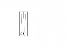
"A large throath to mouth ratio makes the horn bigger with more output and smoother response"
I guess I didnt understand it the first time
I reckon the throath is to be considered as the area at the beginning of the line...and not the compression hole, if thats present
thanks
I guess I didnt understand it the first time
I reckon the throath is to be considered as the area at the beginning of the line...and not the compression hole, if thats present
thanks
Attachments
Just in case anyone is interested, I had decent luck with modelling the discontinued mach5 maw15. Can't remember what I paid way back then but it was dirt cheap, under $150 shipping included IIRC, so people may have these lying around. Mine is currently in use (sometimes) but this looks better...
MAW15 tapped horn, 750w, 280L
Not nearly as much usable bandwidth as the 18sound 15LW1401 that was recommended a couple of posts ago, but max spl is the same or a bit better and this one is "only" 280L, much smaller than most of the designs for 15 inch drivers. I could kill the top 2 peaks more, but as it is it could maybe be used up to 120 if absolutely necessary.
The MAW15 Le is not specified by the manufacturer, but I used 12 mH with .6 rg, so Le would have to be measured and an extra coil added to = 12mH total.
Being an end tapped design at both ends, the only advantage this has over an end loaded tl of the same dimentions is a few extra hz bandwidth which may or may not be used, at the cost of a db or so max spl.
MAW15 tapped horn, 750w, 280L
An externally hosted image should be here but it was not working when we last tested it.
Not nearly as much usable bandwidth as the 18sound 15LW1401 that was recommended a couple of posts ago, but max spl is the same or a bit better and this one is "only" 280L, much smaller than most of the designs for 15 inch drivers. I could kill the top 2 peaks more, but as it is it could maybe be used up to 120 if absolutely necessary.
The MAW15 Le is not specified by the manufacturer, but I used 12 mH with .6 rg, so Le would have to be measured and an extra coil added to = 12mH total.
Being an end tapped design at both ends, the only advantage this has over an end loaded tl of the same dimentions is a few extra hz bandwidth which may or may not be used, at the cost of a db or so max spl.
FlipC said:How would you model that in HR tinitus?
Can you do a mock diagram with same pic?
Wish I knew how to model
Whats a mock diagram...I will do if I can
Attachments

Sorry to be off topic but this whole thread from the very begining seems to be disscussing the finer points of the TH. Could some one please direct me to where I could find the basic priciples of how to design a TH. It's very facinating but I don't know where to start. Thanks.
brsanko
http://www.diyaudio.com/forums/showthread.php?s=&threadid=114340
And
http://www.diyaudio.com/forums/showthread.php?s=&threadid=133710
Also use HornResp as a start point.
A bit back I posted some general start parameters to get HR into TH mode. You can either start with an existing driver and model for it or model a design and see what specs a driver needs to meet your requirements. Though I have found that a PITA because I don't know of a search able DB for specific driver specs. So it is a bit time consuming.
Have fun.
- Home
- Loudspeakers
- Subwoofers
- Collaborative Tapped horn project