As Alice said, "Would you tell me, please, which way I ought to go from here?"
"That depends a good deal on where you want to get to," said the Cat.
"I don't much care where –" said Alice.
"Then it doesn't matter which way you go," said the Cat.
So, the question is "where do you want to get to."
~Don
"That depends a good deal on where you want to get to," said the Cat.
"I don't much care where –" said Alice.
"Then it doesn't matter which way you go," said the Cat.
So, the question is "where do you want to get to."
~Don
djk said:That's why I use AkAbak. I find it easier to do design changes quickly, and see them.
Hi djk,
I would be very surprised indeed if it was possible to optimise a conventional tapped horn design using AkAbak in a shorter timeframe than it takes using the Hornresp Tapped Horn Wizard in conjunction with the Compare tool.
It certainly takes me a lot longer using AkAbak
") .
.Kind regards,
David
Attachments
I dont use Akabak anymore since Hornresp can do everything one needs in order to design a TH - and its alot faster.
The biggest part of the work still is to make a cabinet out of the hornresp values, because in the real world things are not as ideal as in the math world.
The biggest part of the work still is to make a cabinet out of the hornresp values, because in the real world things are not as ideal as in the math world.
hi long time no see
this question is mainly for mikehunt since we both built almost identical horns, just his is abit louder and mine goes abit lower
i find that if i am running my horn at very high levels there is a sorta noise or vibration coming from the speakers magnet, kinda like a pressure noise or summing, like its making a kinda vibrational noise that i think is only audible because it is at a higher frequency than the horn is making but away from the horn u cannot hear it, does anyone else find this with tapped horns?
maybe u have the same issue with yours and its normal, just it sounds like summing lose in the driver but its the same as day 1, maybe i got a slightly dodge driver or make i have stretched it (dont see how)
any ideas?
I've done 5 cabinets from Hornresp data, and they do require some compromise to bring them from the mathematical world to the physical world. Between ProSoundLab and diyAudio, I have "reverse engineered" enough horns to believe that I understand some of the basics.
1. Keep the sum of the bend angles to a minimum
2. Push the bend angles to the small end
3. Each segament of the physical horn has an equivalent segament in the mathematical horn with the same beginning area, volume, and ending area.
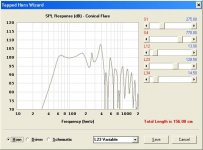
I did a trial fold of MaVo's Lab12, 5.5 meter tapped horn. His sim was flat as a pancake, but he used 3 different tapers, a 1000 sq cm S3, and an L12 of 60 cm. Using a straight taper with MaVo's S1 and S3, the sim was no longer perfect, and the horn was larger than I wanted. The next sim used a smaller S3 (880 sq cm) and shortened L12 to allow installing the driver thru the mouth. The horn came out at 14.5x30x60, which fits nicely with 5'x5' ply, and the compromises came at a cost of 2 Hz and 1 dB.
Anything I missed?
~Don
1. Keep the sum of the bend angles to a minimum
2. Push the bend angles to the small end
3. Each segament of the physical horn has an equivalent segament in the mathematical horn with the same beginning area, volume, and ending area.
I did a trial fold of MaVo's Lab12, 5.5 meter tapped horn. His sim was flat as a pancake, but he used 3 different tapers, a 1000 sq cm S3, and an L12 of 60 cm. Using a straight taper with MaVo's S1 and S3, the sim was no longer perfect, and the horn was larger than I wanted. The next sim used a smaller S3 (880 sq cm) and shortened L12 to allow installing the driver thru the mouth. The horn came out at 14.5x30x60, which fits nicely with 5'x5' ply, and the compromises came at a cost of 2 Hz and 1 dB.
Anything I missed?
~Don
Naudio said:hi long time no see
i find that if i am running my horn at very high levels there is a sorta noise or vibration coming from the speakers magnet, kinda like a pressure noise or summing, like its making a kinda vibrational noise that i think is only audible because it is at a higher frequency than the horn is making but away from the horn u cannot hear it, does anyone else find this with tapped horns?
any ideas?
I get some "air" noise when the flow through the ~2" magnet vent gets fast (in the PD1550 TH from way back in the thread). The only vibrational noise I got was when my access panel was not quite fixed well enough, and that was fixed with more gasket and screws.
The pressures and flows can be quite strong in a TH so it does not need much to go wrong before something buzzes.
Ken
"I would be very surprised indeed if it was possible to optimise a conventional tapped horn design using AkAbak in a shorter timeframe than it takes using the Hornresp Tapped Horn Wizard in conjunction with the Compare tool."
I use both, and for different reasons.
I find AkAback much quicker.
"sorta noise or vibration coming from the speakers magnet, kinda like a pressure noise or summing, like its making a kinda vibrational noise that i think is only audible "
Stamped frame drivers sometimes oil-can at the magnet structure to frame joint, this can make a kink of mechanical 'ticking' sound. Sometimes I run a bead of adhesive into this joint to quiet it down.
Rear vents are usually noisey, sometimes spiders too. Sometimes I tape the rear vents and change the dustcap to a vented (felt) type. On some spiders I have been known to poke a hot soldering iron through them to relieve pressure (Polk used to do this to the apex of the dome on the Peerless KO10DTs). The risk of damage is always there on things like this, use some judgement.
Don Snyder said:1. Keep the sum of the bend angles to a minimum
This seems tobe a compromise one has to do between the frequency of internal resonances and number of bends. The more bends, the shorter the individual segments, the higher the lowest WL/2 resonance. If you have a fixed high cutoff and dont want resonances in passband, that automatically gives you a fixed number of bends.
Oh, and I think you didnt miss a thing with bending this horn
Thanks MaVo,
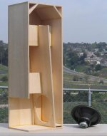
My first answer to the wl/2 problem was to put corner reflectors in the fold area. My KappaLite 3015LF (see pic) did a fair job of dodging the problem, but using a double fold (like your/my LAB12) makes the problem go away.
In the old days (posts < 1000) I did all my trial sims assuming a single fold (Cowan type) using 4'x8' ply. This limits the horn length to 16 feet (less, if you want to get it into an 8' tall room). Also, I didn't want to add the inductor.
This made me give up on the LAB12, but your remarkable sim inspired me to look at it again.
Attachments
Don Snyder said:Thanks MaVo,
My first answer to the wl/2 problem was to put corner reflectors in the fold area. My KappaLite 3015LF (see pic) did a fair job of dodging the problem, but using a double fold (like your/my LAB12) makes the problem go away.
In the old days (posts < 1000) I did all my trial sims assuming a single fold (Cowan type) using 4'x8' ply. This limits the horn length to 16 feet (less, if you want to get it into an 8' tall room). Also, I didn't want to add the inductor.
This made me give up on the LAB12, but your remarkable sim inspired me to look at it again.
So, Don, you are saying that a more optimal fold is possible using the KappaLite3015LF drivers than the single fold that you did a while ago.
What would that optimal fold look like and what would be its simulated response?
Thanks,
Samuel Jayaraj said:
...are saying that a more optimal fold is possible using the KappaLite3015LF drivers than the single fold that you did a while ago.
Thanks,
Optimal? What do you mean? A different fold isn't going to lower the LF cutoff, or increase the sensitivity. It will change some of the resonances, some of the sound characteristics. Things that the sim won't predict. Of course you won't know until you build & test it.
Have you built anything?
~Don
By optimal I meant a fold that more effectively suppresses resonances which will otherwise need either acoustic or active filtering.
Your original fold for the KappaLite3015LF was interesting and simple but the height of the cabinet deterred me from trying it out.
I have built many horns subs and have them all fully functional but I have not yet built a TH.
I have with me a pair each of Lab12 and KappaLite3015LF drivers. I even cut marine grade ply to build Wayne Parham's 12Pi speakers using the Lab drivers but have not yet assembled the whole cab since by then he changed the design a little bit.
If you could please furnish the details of a fold for the KappaLite3015LF similar to the 4015LF fold shown a couple of pages earlier, I would be interested in building them immediately. In fact, I have enough wood to make about 4 to 6 cabs and was going to speak to someone who owns CNC machines in order to have wood cut for the latest version of the Pi speakers which Wayne had sent me a while ago.
Any help with a portable TH using the 3015LF drivers will be much appreciated; by portable I don't mean small or light but not exceeding about 42-45" in height.
Thanks once again,
Hello Samuel - Last time I looked, this was a DIY forum. The information is all here, including post 1490 on how to do a double fold. Also, Volvotreeter has another method on his website.
Since you already have two great drivers, I suggest you build one of the projects as posted, and see how you like it. You may find out (as I did) that the resonances that Hornresp sims aren't there.
Most of us are willing to help, but you seem to want everything done for you.
Sorry, not interested!
~Don
Don, I am sorry if I offended you with my seemingly wanting everything spoonfed. It is just that I am not conversant with any loudspeaker simulation software. I am quite competent in my knowledge of SS amplification design and building and am hence, quite active in the Solid State and Pass Labs forum.
Thanks for your gentle nudge. I guess its time for me to start with available simulation software etc.,
Thanks for your gentle nudge. I guess its time for me to start with available simulation software etc.,
Don Snyder Version of Cowan Horn
Hi there,
I´m one of those "fence sitters" following the thread for a long time.
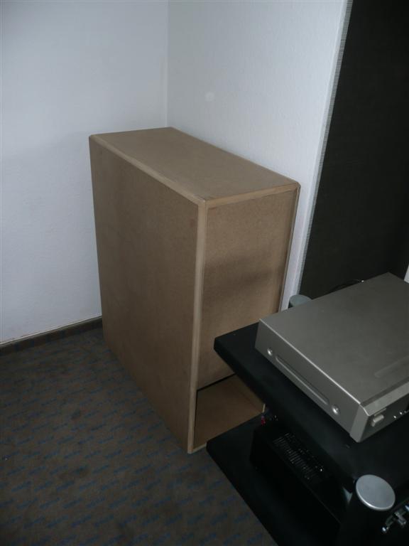
Last week I built the `Cowan`-TH in the `Don Snyder`-folded version.
I really appreciate the work of you guys. The performance of the TH fits perfectly to my main speakers. The best is due to the really tight dimensions it´s almost invisible. (Think it will be painted with wall paint, a curtain will be placed in front of the th.) The WAF is eminently respectable- in this case )
Thanks a lot for this really great construction...
By the way, speaker is a Beyma Power 12 I used a long time in my car.
Hi there,
I´m one of those "fence sitters" following the thread for a long time.
Last week I built the `Cowan`-TH in the `Don Snyder`-folded version.
I really appreciate the work of you guys. The performance of the TH fits perfectly to my main speakers. The best is due to the really tight dimensions it´s almost invisible. (Think it will be painted with wall paint, a curtain will be placed in front of the th.) The WAF is eminently respectable- in this case
)
Thanks a lot for this really great construction...
An externally hosted image should be here but it was not working when we last tested it.
An externally hosted image should be here but it was not working when we last tested it.
By the way, speaker is a Beyma Power 12 I used a long time in my car.
Re: Don Snyder Version of Cowan Horn
Thanks for the update and the pix. I'm glad the Beyma worked out so well. They're good speakers, but expensive here.
This box seems to work well with Beyma, Peerless and Eminence drivers, but I've only done a Hornresp sym with the Definimax 4012 HO. The Definimax is a little short on xmax (6mm).
Does the Beyma have more xmax than the Definimax?
tupaki said:
... I really appreciate the work of you guys. The performance of the TH fits perfectly to my main speakers. The best is due to the really tight dimensions it´s almost invisible. By the way, speaker is a Beyma Power 12 I used a long time in my car.
Thanks for the update and the pix. I'm glad the Beyma worked out so well. They're good speakers, but expensive here.
This box seems to work well with Beyma, Peerless and Eminence drivers, but I've only done a Hornresp sym with the Definimax 4012 HO. The Definimax is a little short on xmax (6mm).
Does the Beyma have more xmax than the Definimax?
How is this different from a transmission-line? It's not a horn!
I would love to be educated in the Tapped Horn principle...but to me, it looks like a modified transmission line speaker, NOT a horn.
The entire principle of a horn is to produce an impedance-matching device, which couples the drivers to the area of air at the mouth. Thus, instead of driving the air in front of the driver, it drives the entire mouth--a much bigger area.
The Tapped Horn has a mouth barely larger than the driver; so how does this work?
- Home
- Loudspeakers
- Subwoofers
- Collaborative Tapped horn project