I was already considering a 10ft to 14ft pipe anyway. Probably 10" in diameter, and I will have almost no choice but to mount it horizontally, next to the ceiling.......
But I just had an interesting thought; How would it change things if most of the pipe, and the drivers themselves, were in the next room over, and only the open end of the pipe came into the listening room, through a perfectly cut hole in the top of the wall (then sealed around the pipe) ???
In other words, kind of a cross between a TL design, and an IB design ?
Just wondering if this might help, hurt, or have no effect either way ?
Your thoughts please,
Fish
Hello Indm....
No. I have built a bunch of tuned port enclosures, and a few sealed ones, mostly for car audio, with just a few for the home, but no TL pipes.
I have been researching the heck out of TL's though, both here on this forum, as well as all over the Internet. It's pretty confusing really, as I have found so much conflicting info. For instance;
I have heard that horizontal pipes are not recommended, AND that they are perfectly okay....
I have heard that the pipe diameter should be no less than the driver diameter or slightly more (like 100% to 110%) AND that a 10" diameter is just about right for most 15" drivers.....
I have heard of successful TL pipes as short as 6ft, and as long as 12ft (14ft if you include the small attached enclosure at one end).
Here on this forum, GM supplied me with a chart which takes driver specs into account. It shows that a 9.7" diameter pipe, by 168" (14ft) would work optimumly with a 15" Dayton Titanic...... but you don't think so ?
I'm certainly not arguing with you Indm, I'm just trying to make sense of all of the conflicting info on TL pipe design.......
Peace,
Fish
Oh BTW Indm, GM also supplied me with a calculator for a "quarter wave" pipe, which is only about 6ft in length. I believe the 168" pipe is for a half wave design.... more efficient ?
Can you imagine how long a "full wave" pipe might be ? ;-)
Re: Hello Indm....
It's just that in my experience (I have built TLs for 4, 5, 6.5, 8, 10 and 12" drivers) I found that the old rule of thumb in tuning the pipe to the drivers resonance often produces weak pipe output. I just wanted you to be aware of this before you punched holes in your walls or you might be punching holes in your walls
Transmission lines have come a long (very long) way in the last less than a decade (although some would say that some smart cookie knew it all along") ). You will have a job to eliminate all of the out of date information that you come across.
). You will have a job to eliminate all of the out of date information that you come across.
With regards to the response of a given pipe (much to the disdain of some), I feel you'd get useful answers from a simulator. You might look toward forum member MJK http://www.quarter-wave.com/ for example.
I have respect for what GM has to say and wouldn't question it.Fish Chris said:Here on this forum, GM supplied me with a chart which takes driver specs into account. It shows that a 9.7" diameter pipe, by 168" (14ft) would work optimumly with a 15" Dayton Titanic...... but you don't think so ?
It's just that in my experience (I have built TLs for 4, 5, 6.5, 8, 10 and 12" drivers) I found that the old rule of thumb in tuning the pipe to the drivers resonance often produces weak pipe output. I just wanted you to be aware of this before you punched holes in your walls or you might be punching holes in your walls
Transmission lines have come a long (very long) way in the last less than a decade (although some would say that some smart cookie knew it all along
). You will have a job to eliminate all of the out of date information that you come across.With regards to the response of a given pipe (much to the disdain of some), I feel you'd get useful answers from a simulator. You might look toward forum member MJK http://www.quarter-wave.com/ for example.
Thank you Indm.....
I guess if the quarter wave pipes were 95% as efficient as the half wave design is, I'd be okay with this. In fact, this would even allow for verticle placement of a couple pipes (one for each of my two 15" subs).
Yes, I have been to http://www.quarter-wave.com/, but all of the examples I saw over there, were for "folded horn" TL's. While I am just really intrigued with the simplicity, and unusualness of a great big pipe organ type of sub woofer horn I couldn't find a straight up "plug in the driver specs, and get a pipe length and diameter", simulator on this site. Is their one that I'm overlooking ?
Anyway Indm, like I keep saying to anyone who has built successful TL pipes, here are the subs I'm strongly considering: http://www.partsexpress.com/pe/pshowdetl.cfm?&Partnumber=295-420
{found then on e-bay a week ago for only $149 each, too !}
And again, I'm looking for lots of bass in the 20 to 40Hz range, with an upper cutoff of between 50Hz and 100Hz... not sure on that aspect yet, as it will depend on whether or not I keep the sub that comes witrh my HTiB, for use as a mid-base driver.
With all respect to other peoples opinions of course, if it were you, how would you design a pipe(s) for two of these subs ? Length, diameter, stuffing ? (keeping in mind I can only get sono-tube in increments of 2"... so 8", 10", 12", etc.
Thank you,
Fish
I guess if the quarter wave pipes were 95% as efficient as the half wave design is, I'd be okay with this. In fact, this would even allow for verticle placement of a couple pipes (one for each of my two 15" subs).
Yes, I have been to http://www.quarter-wave.com/, but all of the examples I saw over there, were for "folded horn" TL's. While I am just really intrigued with the simplicity, and unusualness of a great big pipe organ type of sub woofer horn
I couldn't find a straight up "plug in the driver specs, and get a pipe length and diameter", simulator on this site. Is their one that I'm overlooking ? Anyway Indm, like I keep saying to anyone who has built successful TL pipes, here are the subs I'm strongly considering: http://www.partsexpress.com/pe/pshowdetl.cfm?&Partnumber=295-420
{found then on e-bay a week ago for only $149 each, too !}
And again, I'm looking for lots of bass in the 20 to 40Hz range, with an upper cutoff of between 50Hz and 100Hz... not sure on that aspect yet, as it will depend on whether or not I keep the sub that comes witrh my HTiB, for use as a mid-base driver.
With all respect to other peoples opinions of course, if it were you, how would you design a pipe(s) for two of these subs ? Length, diameter, stuffing ? (keeping in mind I can only get sono-tube in increments of 2"... so 8", 10", 12", etc.
Thank you,
Fish
You will have a job to eliminate all of the out of date information that you come across.
I applaud that comment.
Here on this forum, GM supplied me with a chart which takes driver specs into account. It shows that a 9.7" diameter pipe, by 168" (14ft) would work optimumly with a 15" Dayton Titanic...... but you don't think so ?
Why not!
b
1(1)
Attachments
Re: Thank you Indm.....
A flat impedance and a response falling gently to be 10dB down at 20Hz which will blend well with the room gain of many typical listening rooms. Quite similar to the infinite baffle response. Not bad.
You say you want a crossover at 50-100Hz? Whilst this can be done you may find it a little close to the low end rolloff to come together simply. You may want to go active or increase the frequency.
On the other hand if I were to design a text book TL without having a simulator I would probably do this:
Pipe frequency of 50Hz or 5'8"
Pipe volume of 2.7' ^3 with the start of the line at 4 times the area of the mouth.
3dB down at 38Hz
This may give you a line that suits the driver well but you'd need to consider the suitability of the resultant system for your room. My first guess though is that it may suit you.
bjourno's simulation seems to have done the work for meFish Chris said:With all respect to other peoples opinions of course, if it were you, how would you design a pipe(s) for two of these subs ?
A flat impedance and a response falling gently to be 10dB down at 20Hz which will blend well with the room gain of many typical listening rooms. Quite similar to the infinite baffle response. Not bad.You say you want a crossover at 50-100Hz? Whilst this can be done you may find it a little close to the low end rolloff to come together simply. You may want to go active or increase the frequency.
On the other hand if I were to design a text book TL without having a simulator I would probably do this:
Pipe frequency of 50Hz or 5'8"
Pipe volume of 2.7' ^3 with the start of the line at 4 times the area of the mouth.
3dB down at 38Hz
This may give you a line that suits the driver well but you'd need to consider the suitability of the resultant system for your room. My first guess though is that it may suit you.
Hey Chris, that driver looks a lot more like it, than the Alpine featured in the unhappy chappy thread.
Useing more than one sub tube in your room is a good idea, more even sound than one, room issues ect.
Although my design is old way, ie fs is the length, The results are very impressive and compared to bass reflex, quite easy to get.
If you want to go up to 100hz, it might be a good idea to place the driver either 1/3 or 1/5 the length of the tube for a smother response up higher, similar to boses acustic wave cannon.
I look forward to details of your success soon.
Personally my gut reaction would be not to vent the speaker from the other room. Sound from the front of the cone is as loud as the rear and the idea is to re enforce the lowest frequencies with the combined sound of both, the pipe is to shift the phaseing so that they match. '
Im just speculating! as I don't truely understand the theory. Its quite possible that the shake will pass through the walls. I know at the cinema, that people hear/ feel it through the concrete floor, in the shopping arcade downstairs!!!!!!
Hey Bjorno....
I REALLY appreciate all the great help, with the graphs and such. The first two were of a bit too small file size for me to be able to read the text very easily.... But this latest one is perfect. In fact, I have printed it out, and tacked it to my cork board, right here beside my PC.
Hey, you've already helped more than I could have even asked for (I suspect that doing these graphs must be fun for you
But if you get a few more spare minutes, and if you don't mind, how would the graph for a straight "quarter wave" pipe compare to the longer "half wave" pipe you have posted here ?
And the one that would be even tougher for me to ever figure out..... With both of my Titanic 15"s {because I'm definately getting two of them, to be powered with a nice, big Crown Amp} attached to the bottom of one pipe, like this one: http://www.teresaudio.com/haven/subs/place.jpg (Half wave, or Quarter.... not really sure)
Thanks so much again,
Fish
Re: Hello Indm....
Greets!
ROTFLMAO! So that's why the B#$% Wave Cannon doesn't perform up to par!
As I noted in the other thread and MJK has devoted considerable effort in proving, the pipe's CSA is a function of all the driver's specs, though Vas dominates. That said, if you're wanting a high acoustic power rating (better damping) over efficiency to limit the effects of VC heating, then as is stated in the B@#$ WC patent, a 2:1 CR is a good compromise, so if the 15" driver's effective diameter is 12.75", then the pipe's should be 12.75*0.707 = ~9". For HIFI/HT apps though, we typically want as much efficiency as we can afford in size, so this R-O-T can be ignored.
To get a short TL to go low requires it be reverse tapered with the driver at the extreme top. The price you pay for 'short' is a very large top area since it all comes down to a minimum net Vb is required for a given driver to reach a given Fp. There's no free 'lunch' here, it's a 'robbing Peter to pay Paul' situation.
Right, the Alpha TL is a very basic end loaded 1/4 WL pipe designed to mimic the response of an IB while completely damping the driver's impedance, which is what you asked for AFAIK. Using MJK's Classic TL alignment tables and his WS to sim different alignments will net you more performance overall.
I did?! Please show me. Regardless, a closed one end (or driver), open other end is a 1/4 WL resonator, ergo the 168" pipe is a 1/4 WL pipe. A 1/2 WL resonator would be closed at both ends and have to be ~twice as long to have the same Fp as the 1/4 WL pipe. This alignment can never have more gain than the driver's IB response, but will have the lowest distortion of any alignment other than a 'perfect' horn AFAIK.
GM
Fish Chris said:I have heard that horizontal pipes are not recommended, AND that they are perfectly okay....
I have heard that the pipe diameter should be no less than the driver diameter or slightly more (like 100% to 110%) AND that a 10" diameter is just about right for most 15" drivers.....
I have heard of successful TL pipes as short as 6ft, and as long as 12ft (14ft if you include the small attached enclosure at one end).
Here on this forum, GM supplied me with a chart which takes driver specs into account. It shows that a 9.7" diameter pipe, by 168" (14ft) would work optimumly with a 15" Dayton Titanic......
GM also supplied me with a calculator for a "quarter wave" pipe, which is only about 6ft in length. I believe the 168" pipe is for a half wave design.... more efficient ?
Greets!
ROTFLMAO!
So that's why the B#$% Wave Cannon doesn't perform up to par! As I noted in the other thread and MJK has devoted considerable effort in proving, the pipe's CSA is a function of all the driver's specs, though Vas dominates. That said, if you're wanting a high acoustic power rating (better damping) over efficiency to limit the effects of VC heating, then as is stated in the B@#$ WC patent, a 2:1 CR is a good compromise, so if the 15" driver's effective diameter is 12.75", then the pipe's should be 12.75*0.707 = ~9". For HIFI/HT apps though, we typically want as much efficiency as we can afford in size, so this R-O-T can be ignored.
To get a short TL to go low requires it be reverse tapered with the driver at the extreme top. The price you pay for 'short' is a very large top area since it all comes down to a minimum net Vb is required for a given driver to reach a given Fp. There's no free 'lunch' here, it's a 'robbing Peter to pay Paul' situation.
Right, the Alpha TL is a very basic end loaded 1/4 WL pipe designed to mimic the response of an IB while completely damping the driver's impedance, which is what you asked for AFAIK. Using MJK's Classic TL alignment tables and his WS to sim different alignments will net you more performance overall.
I did?! Please show me. Regardless, a closed one end (or driver), open other end is a 1/4 WL resonator, ergo the 168" pipe is a 1/4 WL pipe. A 1/2 WL resonator would be closed at both ends and have to be ~twice as long to have the same Fp as the 1/4 WL pipe. This alignment can never have more gain than the driver's IB response, but will have the lowest distortion of any alignment other than a 'perfect' horn AFAIK.
GM
Thank you GM....
Okay, so a quarter-wave pipe it will be. Learn something every day
Yes, the Omega quarter wave-length pipe you sent me the calculator for, shows a 71" to 76" inch pipe, depending on whether one uses polyfil or fiberglass stuffing.
Anyway, you said > ....then the pipe's should be 12.75*0.707 = ~9". <
....but again, I can only get sonotube in 8", 10", 12" etc. But now, before you figure out the correction for this, what would be a good length and diameter for "two" of my 15"s, in this kind of setup > http://www.teresaudio.com/haven/subs/place.jpg
Again, I think this is a pretty cool looking design.... plus, the guy says that the push-pull configuration of the drivers made a surprising improvment in overall sound clarity !
(note; there are two drivers in this box, with the driver you can't see, having the voice coil inside of the box.... and one of the drivers being hooked up out of phase)
I'll get this all figured out sooner or later
Thanks again,
Fish
the guy says that the push-pull configuration of the drivers made a surprising improvment in overall sound clarity !
Interesting question, If Vas is infact as important as GM says, should the pipe be 1/2 the diameter? Afterall you cannot reduce the length.
I am also curious about the idea of clamshelling the drivers for push pull, I am under the impression that minimal volume between the cones is the ideal way of doing it. Any thoughts
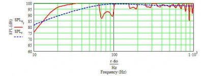
If you put most of the pipe, including the end with the driver, into another room your output will be the dotted blue line below. This is taken from bjornos' sims.
As you can see, the shape of that output will be nice, but the sensitivity will be poor, about 75 dB 1W/1M. So this is not the way to go for a high efficiency sub.
As you can see, the shape of that output will be nice, but the sensitivity will be poor, about 75 dB 1W/1M. So this is not the way to go for a high efficiency sub.
Attachments
Hey guys....
Well Cameron, I think we might be on different pages when we are talking about "push / pull"......
Their is the one type where the faces of the two subs are litterally bolted together, with one sub wired out of phase. This gives half of the cone surface area, of what the two subs by themselves would have. I hear this makes very clean sound, but is not very efficient.
In the push / pull setup I'm talking about, the subs are on opposite sides of the small box at the bottom of the pipe, and are therefor are just as efficient as any "two seperate drivers" would normally be.
Still, I sure would like to know how the pipe might change, for two subs to be attached to it ???
Right on kelticwizard, All in one room it will be then
Peace,
Fish
Re: Thank you GM....
Greets!
You're welcome!
Hmm, when I decided to go ahead and post it I didn't think to change the driver's specs to the Titanic's........good thing you didn't build from it since the actual dims are considerably bigger, 113.46 - 119.65" with much larger CSAs.
Understood. Obviously, you use what's available if you're not going to box it up in wood and since we're usually more interested in best practical efficiency than max damping, then the biggest tubes you can get, but unless you have very high ceilings you won't get to take advantage of the driver's low Fs. Note that with two of these drivers you'll need two 12" tubes 125" long to reach Fs, so at least a 15"h x 24" i.d. square baffle box. Pretty decent half space 2.83 V output or an IB response to Fs if stuffed. The trade-off being a <80 Hz steep XO required if not well stuffed (~1 lb/ft^3 polyfil).
If we drop back to dual 10" pipes to get a slightly smaller box, then performance below ~40 Hz rolls off, though it will only take ~half as much stuffing to get a 'close enough' IB response. If there's decent room gain this is probably a good compromise.
Right, a bipole layout to ~cancel out any rocking coupling motion and drivers physically reversed to average out any suspension non-linearities.
GM
Fish Chris said:Yes, the Omega quarter wave-length pipe you sent me the calculator for, shows a 71" to 76" inch pipe, depending on whether one uses polyfil or fiberglass stuffing.
...but again, I can only get sonotube in 8", 10", 12" etc. But now, before you figure out the correction for this, what would be a good length and diameter for "two" of my 15"s, in this kind of setup > http://www.teresaudio.com/haven/subs/place.jpg
Again, I think this is a pretty cool looking design.... plus, the guy says that the push-pull configuration of the drivers made a surprising improvment in overall sound clarity !
Greets!
You're welcome!
Hmm, when I decided to go ahead and post it I didn't think to change the driver's specs to the Titanic's........good thing you didn't build from it since the actual dims are considerably bigger, 113.46 - 119.65" with much larger CSAs.
Understood. Obviously, you use what's available if you're not going to box it up in wood and since we're usually more interested in best practical efficiency than max damping, then the biggest tubes you can get, but unless you have very high ceilings you won't get to take advantage of the driver's low Fs. Note that with two of these drivers you'll need two 12" tubes 125" long to reach Fs, so at least a 15"h x 24" i.d. square baffle box. Pretty decent half space 2.83 V output or an IB response to Fs if stuffed. The trade-off being a <80 Hz steep XO required if not well stuffed (~1 lb/ft^3 polyfil).
If we drop back to dual 10" pipes to get a slightly smaller box, then performance below ~40 Hz rolls off, though it will only take ~half as much stuffing to get a 'close enough' IB response. If there's decent room gain this is probably a good compromise.
Right, a bipole layout to ~cancel out any rocking coupling motion and drivers physically reversed to average out any suspension non-linearities.
GM
Attachments
Cameron Glendin said:Interesting question, If Vas is infact as important as GM says, should the pipe be 1/2 the diameter? Afterall you cannot reduce the length.
I am also curious about the idea of clamshelling the drivers for push pull, I am under the impression that minimal volume between the cones is the ideal way of doing it. Any thoughts
Greets!
By '1/2 dia.' I assume you're referring to the pipe diameter reduction if the drivers are clamshell mounted. True, Isobaric driver coupling will reduce the baffle box and pipe Vb to 1/4, but the trade-off is 2x the drivers and power to = ~one driver's output, so only worthwhile when saving space is paramount IMO. As always though, YMMV.
Ideally there would be no air gap between them, but a spacer is required to allow for a sub driver's large half roll surround.
GM
- Status
- This old topic is closed. If you want to reopen this topic, contact a moderator using the "Report Post" button.
- Home
- Loudspeakers
- Subwoofers
- Here's an interesting TL pipe question ???