but with your acoustic damper, could it really reduce Qms
Yes its possible for some drivers to reach a Qm=0.8.
First we must try to establish the right use of T/S aberrations like for instance when talking about testing/measuring Qes, Qms or Qts, the convention is that these parameters only are defined for driver that has no connections at all to the physical environment but the free air.
So when you are trying to lower Qms by only shorting your driver, its ok to still target Qms because you don’t make any change at all besides the shorting of a pair of binding posts.
What I have recommended you are to apply acoustic dampening to reduce Qms.
In this case you will not end up with a new Qms but instead a new Qm value for the driver, in this case, when in an enclosure or not, because of the external attached damping material that if calculated in reverse, appears as a T/S Qms value but in reality is not.
Maybe semantics but I think it’s important to understand the difference.
The volume of air between the rear side of the cone and the frame/basket is normally not an obstacle for the releasing of acoustic pressure and as long as there is no blocking, the pressures at low frequencies is equal to the front side.
By blocking, its meant here, that a cavity is formed and the normally open duct is restricted so this driver is no longer a normal free driver that immediate can be characterized by T/S parameters, but a driver in an acoustic circuit formed by the driver and the external blocking material.
For instance if we screen/block about 70 –90 %, it looks like the driver acoustically is put in a very small volume and has a port and the Sd value cant be used directly for T/S calculations anymore at the rear side of the driver and most of the T/S parameters will also change.
There is an earlier posted claim here above that Qms Qes / will also increase for this case, but this can be counteracted both theoretically and with practical proofs as not likely to happen.
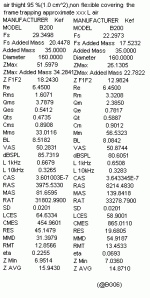
As mention it’s not a new Qms you are measuring but rather a new Qm that for a driver equipped with screens will be lower together with the apparent Qes i.e. Qec that instead will increase, causing the total system electrical Qt value to increase (not the Qts), this can be seen if a temporarily blocked driver is measured.
I’ve waited to post you until now and sorry if Im late, because I’ve been looking for a measurement I made years ago.
Now I’ve found it and this will hopefully show you a proofing of my statements I just made above.
See the picture 1(3) where the driver is about 95 % screened, leaving 1 or 2 cm^2 area open at the binding posts and all the affected parameters that will change and thus thereafter, will not apply for T/S values anymore.
What I’m proposing is a method (acoustic dampening) that is not screening the rear of the driver and that is conserving the properties of the air volume, a volume that only acts as adding an acoustic mass attached to the cone, and in a equivalent electro acoustical scheme will appear parallel with new acoustic resistance (the resistive dampening) that when transformed, is in series with Ras* that causes a driver Qms to a lower Qm.
Not as stated above, attaching an acoustic reactive compliance together with a port with its acoustic properties as will be if just screening or partly covering with cloth with unknown properties.
*In the mechanical view (equivalent) this is equal to an increase the Rms value that will modify Qm (Qms =1/Rms x sqrt (Mms/Cms).
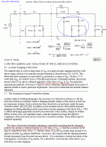
Look at picture 2(3) for the electrical equivalent schematic of a driver that uses acoustical dampening and is in a ported enclosure.
Red is the air resistance that appears and is the acoustical dampening and Cmed is the air mass trapped between the cone and damping material*, that must be attached in a way that not acting as a screen.
The unmarked components is what will be added if the damping material is not secured or what is the equivalent that must be added to the schematic if the damping fibers are moving.
You shouldn’t arbitrarily just attach fibreglass battings and staple them to the baffle or use several layers of cheesecloth’s if you don't have acoustic material measurement equipment like a tube absorption meter in your workshop so you can verify that your acoustic dampening is resistive within your low frequency application bandwidth, thus a secure measure taken in order to avoid to clogging and not just screening your driver to something unknown.
*The damping material fibres, inexpensive fiberglass type is recommended (density = 20(+) kg/m^3) and must be carefully applied with the fibers as perpendicular as possible to the rear side of the cone and also to the baffle where its glued.
It takes some DIY time to orient the fiber pieces into a new battens where most of the fibers are parallel if not a more sophisticated acoustical material is used that surely will be more costly than the few cent for the recommended.
When done correct, a mostly resistive damping material is formed and when used will decrease Qm and also Qt.
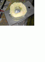
The picture 3(3) shows an application that works and is from a Swedish source where also the most of the content in picture 2(3) is fetched.
b
1(3)
Attachments
Hi Anders,
you're right, proofed by your test. Ron E right, Dan Wiggins right too.
Parallel, series and one coil shorted, Qts remains at the same value.
Hi Bjorno,
that's very deep explanation you wrote! I must chewed it slowly to understand since I knew very little of this matter.
I rather confuse about Qms, Qes and Qts, it change to Qm, Qe and Qt, is it a new value of Qms, Qes and Qts?
In other words:
Can I measure T/S param as a normal driver after putting the damping material, and get all new T/S param from it?
chris.
Bjorno, I am very interested in this method if indeed qts can be lowered for any driver. Unfortunately I am not as smart as you and I cannot understand most of your post above, as well as picture 1 and 2. Picture 3 is unclear and it looks like a regular sheet of fibreglass insulation rolled into a circle and loosely clamped to the driver.
Is that right? Is that the method you are recommending?
In the other post you linked to on page 2 of this coversation you said "fitting a 3-4 inch thick cylinder of glass fiber or mineral wool, (1.25 -1.5 lb/ft3 glued Liquid Nail type) to the rear side of the baffle adjusted to completely covering the rear outlets of the driver. The fibres must be oriented perpendicular to the baffle, also letting air to be passed through without any fibre moving.
Fibre-cylinder inner diameter is equal to the magnet diameter and the latter has also some glue on the surface for fastening the wool securing unwanted fibre movement. The length of the cylinder is about equal or slightly longer than the formed cylinder outer diameter."
I'm not able to picture this setup. Is it like picture 3 above? I'm not sure exactly what you are recommending, could you make it more clear please?
- Status
- This old topic is closed. If you want to reopen this topic, contact a moderator using the "Report Post" button.


