I had another thread in car audio about exactly what to do (http://www.diyaudio.com/forums/showthread.php?s=&threadid=86171) and while I thought I had made up my mind to go with sealed boxes, I really hadn't. Good thing I didn't actually start building.
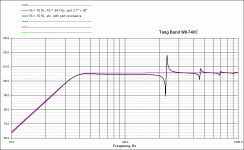
I have the TB W8-740C 8" subs. From what I can tell, a small ported enclosure is the best for these but every time I ran the numbers, I came up with an insanely long port length. After messing with some of the parameters and going with a less-than-optimal volume and a little bit lower tuning, I was able to come up with a box of 10.9L and a port with 5.5in^2 and about 30" long (34.8Hz).
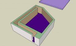
I came up with what I think is a design that will work, then downloaded Google's Sketchup software so I could model it to show to you all what it would look like and ask if there are any problems with it. I've never had to build such a strange box before so I want to know if I'm screwing it up.
When you measure the port length, do you just measure a line through the middle of the port path?
The port is 2" wide and 2.75" deep. The chamber with the driver is 4.25" deep. I will round off all the edges of the turns in the port path and will put a little bit of fill just around the driver.
I can't figure out how to attach more than one picture, so they're here:
http://home.houston.rr.com/lothar/GTO.panelbox.ported.1.jpg
http://home.houston.rr.com/lothar/GTO.panelbox.ported.2.jpg
http://home.houston.rr.com/lothar/GTO.panelbox.ported.3.jpg
http://home.houston.rr.com/lothar/GTO.panelbox.ported.4.jpg
http://home.houston.rr.com/lothar/GTO.panelbox.ported.5.jpg
An externally hosted image should be here but it was not working when we last tested it.
Lothar34 said:
When you measure the port length, do you just measure a line through the middle of the port path?
Yes, looks ok to me.(nothing obviously messed up)
I think it'll be OK. The chamber where the driver is mounted is supposed to be 10.9L (or 665 cubic inches). The way it is in that model, it is 466 cubic inches net. That's about 70% and I can make that up with fill. I still have an inch laterally to play with too, so I could stretch it out and get it to 515 cubic inches (77%) and use less fill. I'll probably do that actually. I can't wait to get started on this... 
You cannot make it up with fill on a ported design
Fill does not work quite the same on a ported design. On a sealed design you can stuff it and make up the lack of volume. On a ported design the stuffing must not obstruct any area between the driver and the port.
Lining the walls helps on a ported design, but I don't think you can make up anything like 30% as you might be able to on a sealed.
Re: You cannot make it up with fill on a ported design
Well will it make up 23%? I knew better than to block the path to the port, but I thought it still worked the same as in a sealed enclosure. I should be able to get a good amount along the walls and in those corners. If the baffle is a lot larger than the driver, are you supposed to put some on the back side of the baffle too? On the other boxes I've done the baffle was barely bigger than the driver and it wasn't really possible, so I'm not sure if you're supposed to put any there or not.
The way that picture is, the blue top portion is 11.75" wide across the top, but when I build it it will be 1" wider.
Thanks for the comments.
EDIT:
I just checked in Unibox and it says there's a bit of a loss between 30 and 60Hz when the box size drops that much, regardless of the amount of fill. So I will try to figure something else out.
jmiyake said:Fill does not work quite the same on a ported design. On a sealed design you can stuff it and make up the lack of volume. On a ported design the stuffing must not obstruct any area between the driver and the port.
Lining the walls helps on a ported design, but I don't think you can make up anything like 30% as you might be able to on a sealed.
Well will it make up 23%? I knew better than to block the path to the port, but I thought it still worked the same as in a sealed enclosure. I should be able to get a good amount along the walls and in those corners. If the baffle is a lot larger than the driver, are you supposed to put some on the back side of the baffle too? On the other boxes I've done the baffle was barely bigger than the driver and it wasn't really possible, so I'm not sure if you're supposed to put any there or not.
The way that picture is, the blue top portion is 11.75" wide across the top, but when I build it it will be 1" wider.
Thanks for the comments.
EDIT:
I just checked in Unibox and it says there's a bit of a loss between 30 and 60Hz when the box size drops that much, regardless of the amount of fill. So I will try to figure something else out.
After a quick look I think it looks ok, it will work. However, remember that this port, just as any, will benefit from rounded edges at the in- and outlets. You may also want to make it possible to tune the port slightly when you find that it does not match the simulation perfectly. This can be done by adding a piece of MDF on the walls of the port to make it narrower (lowering fh) or by making the openings bigger (raising fh).
And remember to round the edges of everythng that is passed by a high air velocity.
And remember to round the edges of everythng that is passed by a high air velocity.
Yeah I've got a router and am going to round off all of the outside and inside corners along the port path. Once the thing is assembled though, I won't be able to get it apart easily to change the port dimensions.
I made a different design last night where I can get the full 10.9L plus the port, but it's horribly complicated and there's just too much room for error with all the cutting. I'm going to try to see if I can come up with a simpler design tonight.
I made a different design last night where I can get the full 10.9L plus the port, but it's horribly complicated and there's just too much room for error with all the cutting. I'm going to try to see if I can come up with a simpler design tonight.
Pipe resonance
I see the first quarter wavelength pipe resonance in the port is around 110 hz. Over what range do you plan on using this sub? If it's a 4th order crossover at or below 80 hz, it shouldn't be too bad.
That's the tradeoff with longer ports... they let you have higher diameters that help reduce port noise, but at a certain length you have to worry about pipe resonance.
WinISD Pro Alpha shows the first pipe resonance for you. I just calculated 110 hz by hand based on a 30 inch port.
I appreciate it.
The amp has a 12dB/oct Butterworth crossover built in and I was going to cut it off between 90-100Hz. I was going to get it in the car first and do it by ear. I want to cut it off below the cabin's resonant frequency, which I think is somewhere around 95Hz.
The amp has a 12dB/oct Butterworth crossover built in and I was going to cut it off between 90-100Hz. I was going to get it in the car first and do it by ear. I want to cut it off below the cabin's resonant frequency, which I think is somewhere around 95Hz.
Oh, nice. See, I wasn't sure if the first resonance was at quarter or half wavelength. Looking at that, I guess it's half. Shouldn't be too bad,but could be better.
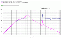
If you cut at 80 hz and the resonance is near 240 hz, that's down 15 db at the resonance. Can you add the highpass to your unibox simuation to see what the final response will look like? If you could get the resonance down 20 or 25 db, that would be better. Any effort to suppress it much more than 25 db would probably be wasted effort.
If you cut at 80 hz and the resonance is near 240 hz, that's down 15 db at the resonance. Can you add the highpass to your unibox simuation to see what the final response will look like? If you could get the resonance down 20 or 25 db, that would be better. Any effort to suppress it much more than 25 db would probably be wasted effort.
Lothar34 said:I'm not sure what you mean by "add the high pass." Do another graph for my mids and tweeters?
Sorry, I mistyped. I meant "low pass". If you add the effect of the low-pass to your graph, you'll see how far down the response is as the point of that port resonance, giving you some idea of how noticeable it is.
Lothar34 said:Lemme ask this too - does the port need to be close to square? Would it be bad to make the cross section 1.25" x 4.25" instead of 2" x 2.75" like I was planning?
Ports that are farther from round will have more resistance to air flow. It's probably less of a factor than the problems you'd have from sharp corners and unrounded port openings, but I wouldn't make the ports any narrower than that.
Well that ruins the design I came up with last night.joe carrow said:
Ports that are farther from round will have more resistance to air flow. It's probably less of a factor than the problems you'd have from sharp corners and unrounded port openings, but I wouldn't make the ports any narrower than that.
joe carrow said:
Sorry, I mistyped. I meant "low pass". If you add the effect of the low-pass to your graph, you'll see how far down the response is as the point of that port resonance, giving you some idea of how noticeable it is.
I'm not sure I'm doing this right. I put in the values for Lco1 and Cco1 that would make a second order LP filter at 95Hz (I put 0 for the series resistance 'cause I have no idea what that would be) and the graph has a huge peak at around 70Hz. Is that normal for a passive crossover? If so, that may not be realistic because the crossover is built in to the amp, and it may not be passive (all it says is 12dB/oct Butterworth). On top of that, there's a crossover for the sub output from my headunit. I don't have the manual handy so I don't know what frequency or what the rolloff is, but the effects of the two crossovers are somewhat additive, right?
Attachments
The amp's built-in crossover is active. It won't have any sort of a bump like that, and will have minimal interaction beyond the desired effect of a lowpass cutoff.
If you fed a sub output from a head unit to an amp with a built-in crossover, then it will depend on if the sub output has a lowpass or if it's a full range signal. You'll want to check the manual for that.
I wouldn't count on it. A slot port that's 1.25" thick probably wouldn't obstruct the flow too badly if it only has one bend in it. How about a compromise, and do 1.5 or 1.75?
Some forum and google searches for "slot port" should help you find some good rules of thumb for how narrow you can make it, as well as bends and rounding. Good luck!
If you fed a sub output from a head unit to an amp with a built-in crossover, then it will depend on if the sub output has a lowpass or if it's a full range signal. You'll want to check the manual for that.
Well that ruins the design I came up with last night.
I wouldn't count on it. A slot port that's 1.25" thick probably wouldn't obstruct the flow too badly if it only has one bend in it. How about a compromise, and do 1.5 or 1.75?
Some forum and google searches for "slot port" should help you find some good rules of thumb for how narrow you can make it, as well as bends and rounding. Good luck!
I checked the manual online and for some dumb reason it doesn't say if it's crossed over. Crutchfield's site says this though:
The reason I went with 4.25" x 1.25" was that the internal height is already 4.25". If I lower that for the port, then I have to cut a big L-shaped piece for this design (attached) and I would also have to move stuff around to get the full 10.9L where the driver is.
EDIT:
and the crossover effects are additive right? It seems to me that they would be. If the frequencies coming from the headunit are sloping down, then the amp's crossover would just take what it's given and drop them some more, right?
The KDC-X590 is equipped with a pair of subwoofer preamp outputs. The subwoofer outputs can easily be turned on/off. When the subwoofer output is turned on, you can adjust the volume (-15 to +15 in increments of 2), set the low pass filter cutoff (50Hz, 60Hz, 80Hz, 100Hz, 120Hz, or Through), and the phase (normal, reverse).
The reason I went with 4.25" x 1.25" was that the internal height is already 4.25". If I lower that for the port, then I have to cut a big L-shaped piece for this design (attached) and I would also have to move stuff around to get the full 10.9L where the driver is.
EDIT:
and the crossover effects are additive right? It seems to me that they would be. If the frequencies coming from the headunit are sloping down, then the amp's crossover would just take what it's given and drop them some more, right?
Attachments
- Status
- This old topic is closed. If you want to reopen this topic, contact a moderator using the "Report Post" button.
- Home
- Loudspeakers
- Subwoofers
- Any inherent problems with this enclosure design?


