is there any difference in the two designs performance wise ??
i am ( again ) slowly planning winter projects,
and i am considreing all dipole system
( manger on top and 2 15" on bottom...stereo )
I've seen alot of people using Linkwitz H frame design
and only a few talk about W Frame
Then, would a W frame work correctly if on the side??
( ie the 2 drivers on top of each other ...like having it rotate 90deg
on the Z axis )
Also beeing there, how high QTS should i look for in dipole woofers? is long excursion desirable? ( should be crossed at 150-250hz ..to be determined )
Was looking at either McCauley or Belisle Accoustics subs
( the mcCauley 18" are very very very very tempting again .. )
thanks again all for your time!")
i am ( again ) slowly planning winter projects,
and i am considreing all dipole system
( manger on top and 2 15" on bottom...stereo )
I've seen alot of people using Linkwitz H frame design
and only a few talk about W Frame
Then, would a W frame work correctly if on the side??
( ie the 2 drivers on top of each other ...like having it rotate 90deg
on the Z axis )
Also beeing there, how high QTS should i look for in dipole woofers? is long excursion desirable? ( should be crossed at 150-250hz ..to be determined )
Was looking at either McCauley or Belisle Accoustics subs
( the mcCauley 18" are very very very very tempting again .. )
thanks again all for your time!
You should like that.and i am considreing all dipole system
Both are more compact than a flat baffle. They trade cavity resonances that limit their upper frequency response for compactness. The W is more compact, somewhat harder to build and may be somewhat more high frequency challenged.I've seen alot of people using Linkwitz H frame design
and only a few talk about W Frame
IME Qts of .5 is Ideal. Lower than .5 requires additional equalization. Higher can compensate for OB roll off and should be considered an engineering decision. I have seen woofers of Qts as low as .3 used successfully, and I would consider a Qts of .8 as my personal maximum. If you have reasonable H or W enclosures, you are going to require Equalization. As long as this is true, you need as much excursion as practical. At this point, you are balancing distortion, cost, efficiency, size and excursion.Also beeing there, how high QTS should i look for in dipole woofers? is long excursion desirable? ( should be crossed at 150-250hz ..to be determined )
Good luck;
Doug
I second Doug in all his arguments,
and dare to give a rule of thumb:
Up to 150 Hz x-over W-frames may be fine. For anything above that you should build an H-Frame (while this will need more EQ bass-wise). Since taking a dipole bass up to 200 Hz is a good idea in every respect , I would vote for the H-frame.
Rudolf
and dare to give a rule of thumb:
Up to 150 Hz x-over W-frames may be fine. For anything above that you should build an H-Frame (while this will need more EQ bass-wise). Since taking a dipole bass up to 200 Hz is a good idea in every respect , I would vote for the H-frame.
Rudolf
i thank you both for your sharing ..
is the only advantage of the W frame compactness compared to the H ??
i am still unsure as to QTS
when a driver has a higher QTS, does that means
trade offs on other parameters/performance??
Can the cavity resonnance be predicted?
i also wonder if there would be any benefit in using rounded off sides for the enclosure? ( round ends on each side of the enclosure where the wave meets ... )
i will do both type in 3d later on and see what i can get off the feeling of it!
Another characteristic of the "W"-frame construction is force cancellation. The two cones are always moving in opposite directions so vibrations imparted to surfaces...like the floor...are minimized.
A typical W-frame construction would be somewhat "squareish" when viewed from the front so I don't see any reason to orientate the drivers horizontally. Cone sag could become an issue in that case.
You can make a fairly good estimation on the cavity resonance based on the depth, but you need to confirm it with a close-up measurement once constructed.
Cheers,
Davey.
Not necessarily, but:Originally posted by JinMTVT
i am still unsure as to QTS
when a driver has a higher QTS, does that means
trade offs on other parameters/performance?
High Ots can be had for less money than low Qts. So many cheap drivers "feature" high Qts values along with other money-saving " attributes".
For the Phoenix W-baffle Linkwitz reports very different cavity resonances (190/270 Hz) for two different drivers (Peerless XLS 12 / Madisound 1252 DVC) in the same baffle. So I believe there is no really easy way to predict it.Can the cavity resonance be predicted?
It´s still not clear to me, what exactly you mean. May be a drawing would help.i also wonder if there would be any benefit in using rounded off sides for the enclosure? (round ends on each side of the enclosure where the wave meets ... )
An externally hosted image should be here but it was not working when we last tested it.
fig.1a demonstrates what i talked about,
using rounded off enclosure edge
would there be any benefits to doing that?
would there be any benefits in rounding all the edges inside the enclosure also ?
fig.1b shows different enclose side angles
would that have any benefit in the resonnance department ?
i have learned from experiment that using never perfect and paralell angles for construction almost always pays off somehwere in the audio !!
please excuse the humble drawings
hope you see what i mean !!
I am using a pair of these 12's, sourced from a great guy in Western Canada, in open baffle.
Each 12 is located at the bottom of a 36w x 48h baffle, in which lives a Visaton b200 full ranger.
By running the 12 on only 1 of the two voice coils, you double the effective QTS from 0.38, to a very nice (for OB) 0.76... good XMAX, good FS, good for OB!
http://www.mach5audio.com/product_info.php?products_id=41&osCsid=df22114511d5b9b07ea425a028ed2259
under $65 each, shipped, in Canada, and great performance in OB...
Well worth a look,
i am not sure that i get your point
else than pointing out to this driver and website
where are those drivers manufactured ?
i'd like to buy from TRA if possible,
as their drivers are all manufactured here in Quebec!!
and they seem to have seriously good quality
second choice was 18" from McCauley
but 18" will have a huge footprint and i can't really afford that in my room
( the 18" will have to wait for the new house theater room )
thanks neway for pointing this site out !!
Originally posted by JinMTVT
please excuse the humble drawings, hope you see what i mean !!
Certainly I get it now. And no - rounding the enclosure edge will have no benefit. The length of a 100 Hz wave is 3.14 m, so it doesn´t "see" such a small extension. This is even more true for any edges inside. Rounding them off is only for aesthetical reasons.
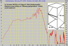
A W-frame like yours will have a quarter wave resonance almost at lambda/4 = depth of W. A H-frame would have its resonance at double that frequency. So you will be pushed hard to get that W-frame up to 250 Hz. Have a look at mine:
http://www.diyaudio.com/forums/attachment.php?s=&postid=1013862&stamp=1159221400
And this is the nearfield frequency response:
Attachments
nice nice Rudolf,
i hear you!
what about making the sides not paralell ?
will that have any benefit on resonnances of the upper region ?
since it will be used with manger, i could see them going up to 200-250hz at max
probably crossed at 150hz where i'll feel that the manger starts going down
or heck, i'll just ghet the manger, make the baffle
and measure it before i construct the woofer enclosures...
So rounding off the edge is only good in baffle or box with HF operating range, for dispertion right ?
Then i can see from your drawing that you are using it with the 2 drivers on top of each other?
is that a good way to use it ?
then from your graph, ur system doesn't go down as soon as i would've thought ..
still going strong past 300hz nah ?
i am not sure i understand how to measure the wavelength effective for the enclosure of the H and W
do we measure the tour around the enclosure side sarting from the driver or we only use the measure of the width of the enclosure?
thanks agian for your time
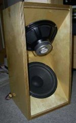
I have two 18 inch drivers (Ascendent Audio Avalanche drivers)in "W" baffle (phoenix style with one driver mounted in line with the other, not offset at 90 degrees like your diagram shows) and two 15 inch drivers on "U" baffles (mounted on the same baffle as the midrange drivers which in my case are Lowther DX4s).
The commenters are right that the W baffles tend toward resonances (mounting them at angles that you show would help to increase the frequency that the resonances occur). When I low pass them at 100 hz with a 24 db/octave filter, I avoid most (all?) of these resonances. But I tried one configuration where I crossed them over using a 12 db/octave filter at 250 hz and these resonances were clearly audible.
I don't know that the U baffles had similar resonances, but certainly they were less than the W baffles at the frequencies that they occurred.
I had significant problems with the U baffles shaking significantly, despite the bracing I was using (they are made out of 3/4 inch conventional plywood) when they were the sole drivers I was using. When I construct a final baffle and if I continue to mount thes 15 inch drivers in this fashion, I will at least double and maybe triple up the thickness of 3/4 inch material that I use for this baffle. This is one of the reasons I why picked up the pair of 18 inch drivers and mounted them in the separate boxes.
The W baffle is constructed out of 13 ply birch plywood. The baffles that the drivers are mounted on are 1 1/2 inch thick while all other faces are 3/4 inch ply. This thing is about 21 inches high, 24 inches deep and 40 inches wide (I suppose I could have made it narrower, but I did not want to increase the Q, I was hoping to avoid resonances, and I wanted to create a TV stand out of it). Playing very dynamic CDs (i.e., drums), any lighweight items sitting on the box can shake off it which demonstrates that the panels can still vibrate despite the cancellation benefits it enjoys. It weighs 160 pounds (80 pounds for the box and 80 pounds for the drivers). If I keep it for the long term, I will double up on all the 3/4 inch panels which will reduce its vibrations significantly.
I am planning to make a rectangular box that I will bolt onto the back side which has the common vent for the two drivers. The sounds being emitted from the drivers off that side of the box will have a lot longer distance to go before the sound can cancel. Once I have this in place, it will increase the equivalent baffle width from 24 inches to 60 inches (it will create a hybrid W-U baffle), thus providing significantly deeper bass extension.
Retsel
TRA / Belisle Acoustics...
http://www.tr.ca/2006/english.htm. some nice looking drivers. Regards Moray James.
http://www.tr.ca/2006/english.htm. some nice looking drivers. Regards Moray James.
Retzel,
I believe you're definitely on the right track adding the extension to the back. Not only do you pick up the extra rear wave travel distance on a 2 for 1 basis, but dipole bass is extension limited by the room's fundamental resonance, which the cardioid characteristic resulting from the U hybrid helps avoid. I've had great results with my W/U baffle hybrid test boxes using cheap drivers. I look forward to doing something similar with quality drivers.
Jin & Rudolph,
Once you get that kind of splay in your panels, I don't believe 1/4 wave resonances can exist. GM told me anything greater than 1" per 6" of depth should avoid resonance. The parallel top and bottom panels are a problem though. Something that will help avoid resonance (mentioned by DJK for boxes with manifolds) is to fill in the deep corners both front and rear with angled wood or rigid fiberglass.
As Retzel mentioned, you need a lot of mass to avoid vibration. Also, even though the box isn't closed you've got to address panel vibrations. Closed box alignments don't have panel vibrations due to a change in absolute pressure changes in the box, it's due to the pressure waves striking them with significant force. The angled alignments pictured will help, but the forces are still significant.
In a pure dipole alignment like Rudolph's pic, the distance differential is only the depth of the cab. The part you can't really quantify is the floor benefit, which is more than just boundary loading. The difference to measure is the travel distance of the rear wave from the cone to your listening position vs the travel distance from the front of the cone to your ears. That's why a U-baffle is +6db at the bottom over a same dimension H-baffle, because the "D" is doubled, which moves the F-equal point down a full octave.
BTW, as far as bass is concerned, nearfield measurement means little for any OB alignment because it greatly discounts the effect of the rear wave both in terms of spl vs distance as well as the front/rear wave travel differential.
john...
nice comments
For the measurements of differential
u say that it is the difference in distnace between the listener's ear and the front VS rear cone ?
does that account for going "around" the baffle
or straight hypotetically through the enclosure and difrectly to the cone ??
The non paralell edges would help ?
but by doing what exactly ?
Transition designs...
JohninCR: would be interested to know what specific drivers you have had sucess with. Chops has used inexpensive Pyle drivers and another source of inexpensive yet suitable drivers was posted here http://www.mach5audio.com/product_info.php?products_id=41&osCsid=df22114511d5b9b07ea425a028ed2259.
Inexpensive driver will make experimentation with dipoles of all kinds more accessable to builders who might take the plunge and start building if the price was right.
I did want to ask you about your comments on regarding small amounts of angle being introduced to normally parallel drivers especially the parallel top and bottom of "W" style dipoles. First am I reading correctly that you are suggesting lengths of small 45 degree filler blocks the depth of the cabinet be used to break up resonances? So all around the inside cavity where the two drivers fire into ("W" style cabinet)? I wonder if resonances in this band are not more a result of the basket which is inserted into the cavity than the cavity itself, just a thought. I have not read anything about such resonances being an issue with Ripole versions. Please note though that most of the posted information (so far) on Ripoles is in German and I have to depend upon Google tramslations so the text is not a wholey reliable translation.
As you start to add angle between the two drivers then you start along the path which will lead you to a flat baffle with a driver on each side. So one extreem of that line is a "W" dipole and the other a "H" dipole. It would seem that for a "W" dipole to work then the fundamental cavity resonance needs to be preserved since in that design you have a short 1/4 wave duct on each face of the driver. The benefit of the driver cones firing at each other generates compression which increases the resistive load on the drivers which also happens when you angle the drivers in a "V" orientation in a "H" dipole though to a lesser degree. This results in the decrease of the drivers Fs when mounted in a "W" or Ripole cabinet. (Question: are similar reductions in driver Fs also observed in "H" dipoles?). From what I have read so far (perhaps Rudolf or Calvin will comment on this) it would seem that the sub's polar patern can be manipulated into a cardioid or perhaps more correctly into a more cardioid polar patern than purley dipole one.
Your comments on these thoughts will be most welcome. Regards Moray James.
JinMTVT said:For the measurements of differential
u say that it is the difference in distnace between the listener's ear and the front VS rear cone ?
does that account for going "around" the baffle
or straight hypotetically through the enclosure and difrectly to the cone ??
The non paralell edges would help ?
but by doing what exactly ?
Jin,
The rear wave can only go around/over the baffle. You have to keep in mind that Linkwitz's 6db/oct and starting point is free space. Once you get in room it's a whole different ball game. You've got the benefit of the floor, which is significant. You also have placement from the rear wall, which with judicial placement can increase bass from the predicted free space response. Use Linkwitz's SPL max spreadsheet as your starting point, then like any good engineering design you have plenty of cushion.
Re: non-parallel panels, I'm talking about all of the vertical panels in the drawings. If they aren't parallel, 1/4 wave &/or 1/2 wave resonances are going to be hard to stimulate. Panel resonances would be a much greater concern, because bracing is difficult but necessary.
Moray,
I bought a 20 Nippon 12" woofers that I found locally for $12/ea. I'd have trouble recommending them because I found them only once online but for over $20 and they aren't worth it especially plus shipping (too easily banged against the back plate). I built 2 cabs of four 12's each in a W/U hybrid using the Ripole approach of small pathways. They sound great with my only problems for below 100hz use being panel vibrations and output limitation due to Xmax.
Especially because OB's are open, parallel surfaces need consideration (more important than with boxes). Then if you have a manifold, you have to worry about depth. If surfaces are far from parallel, as I understand, 1/4 wave resonances can't be a problem, however, depending upon placement, reflections off of the rear wall can create cavity resonances.
Yes on the filler blocks, but only in those deepest corners to break up the rectangle shape of the cavity. Also, it seems intuitively better to have that air forced out of the pathway instead of compressing in that otherwise dead corner.
I have 4 Hawthorne Augies for my next attempt at high output OB bass augmentation needing only subwoofer assistance for HT. I want to construct a pair of units that will also be a solid base for whatever OB solution I want to put on top. Mechanical cancellation is a must. Push/pull with equal time alignment is another given. I also want to be able to use them up to 200hz or higher, to give me flexibility on drivers to use above that. Although I plan to use a slightly angled W alignment, for minimum width and lowering Fs reasons I want to try to get as close to a double ripole as possible. Plus I want to keep the splay angle of the drivers to a minimum for mechanical cancellation reasons. For upper end extension, I'll concede some added height to completely avoid parallel panels within the cavities, and utilize the resulting top and bottom voids to add mass and act as bracing and damping. I believe I can get 100db+ at 30hz potential fitting the pair of 15's in a cab 21" tall, 20" deep (including a U extension in the back), and close to 12" wide, while hitting all of my targets. My biggest problem, other than the construction complexity that angles create, is making sure I can mount the drivers once they're built.
Originally posted by johninCR
Once you get that kind of splay in your panels, I don't believe 1/4 wave resonances can exist. GM told me anything greater than 1" per 6" of depth should avoid resonance.
John,
the initial impulse to build my W-frames was the hope to avoid that lambda/4 resonance - exactly on the reasons you have stated. But – with all respect for GM – it doesn´t work like a switch you can turn at certain angle values and get rid of that resonance.
Compared to the same drivers in ripoles the resonance is “smeared” somewhat, but in hindsight I would have liked it more to be small and well defined so it could be “notch filtered” better. If I had to do it again I certainly would do one of the purer principles: either a conventional W-frame / ripole or a conventional H-frame.
The 300-400 Hz resonance peak of my W-frames surely results from the depth of the frame and NOT from the height or width, since the depth is building the only cavities to speak of in the design, that can be correlated to 300-400 Hz.
So changing the left and right panels in the way JinMTVT has illustrated in fig. 1b will change almost nothing compared to fig 1a. He will have to make the outermost angles almost 90° to make a difference.
BTW, as far as bass is concerned, nearfield measurement means little for any OB alignment because it greatly discounts the effect of the rear wave both in terms of spl vs distance as well as the front/rear wave travel differential. [/B]
That´s true for sure. My nearfield measurement was only meant to illustrate the resonance.
Rudolf
Attachments
When it comes to 1/4 wave resonances I can only go by what a TL expert like GM would tell me, since I don't really understand how they work.
In looking at your latest pic with the vertical dimension being the longest, my gut reaction is that the resonances in question are panel vibrations in those side panels. Just look at the size of those unbraced and undamped panels. I bet they vibrate quite audibly.
A complete lack of bracing is pervasive in virtually all folded OB designs I've seen, and it's based on the widespread misconception that since the cab is open there is no pressure exerted on the panels. This is simply not the case. In fact, because the front and rear edges of OB's typically don't have the structural support of a corner like boxes do, one could make the case that bracing is more important with folded OB's than with boxes. You do have to be more careful in how you orient your bracing than with a box, because you want to ensure that the pressure flow is equal on both sides of any braces.
I learned the hard way when I built a pyramid shaped U-baffle. With no bracing the large panels vibrated quite audibly. Then I added relatively small rectangular panels as cross braces. It cleared up the side panel vibrations, but the cross braces sang like guitar strings because the pressure flow wasn't equal over the top and bottom of the panel braces. Rod type braces with damping is probably the way to go with odd shaped cabs.
- Status
- This old topic is closed. If you want to reopen this topic, contact a moderator using the "Report Post" button.
- Home
- Loudspeakers
- Subwoofers
- W-Frame or H-Frame dipoles? performace issues?