Johan,
My only direct comparison with push/pull and non-push/pull pairs was using cheap 12" drivers. The audible difference was more than subtle even at only moderate volumes, where distortion should be low. I speculate that more than just linear operation of the cone is involved, and the sound from the back of the driver is different due to influences of the basket and magnet structure, plus even the Sd is different. A push/pull alignment ensures that these differences are balanced out.
My only direct comparison with push/pull and non-push/pull pairs was using cheap 12" drivers. The audible difference was more than subtle even at only moderate volumes, where distortion should be low. I speculate that more than just linear operation of the cone is involved, and the sound from the back of the driver is different due to influences of the basket and magnet structure, plus even the Sd is different. A push/pull alignment ensures that these differences are balanced out.
"My only direct comparison with push/pull and non-push/pull pairs was using cheap 12" drivers."
The cheaper the drivers, the more push-pull will help them.
"Are there any (more or less) exact figures you can talk about when it comes to reducing distortion with push pull? And/or how much of a noticeable difference (to the ear) are we talking about?"
Some old comments cut&pasted from elsewhere(sorry, the link is dead):
Kind of like this:
http://cgi.ebay.com/ws/eBayISAPI.dll?ViewItem&item=73392 75215&category=47094&rd=1
This was a box EV came out with after I talked with one of their engineers at a trade show about 20 years ago.
EV showed me the light in 1974 with the Interface A, an SBB4 alignment with a Q=2 filter ahead of the amplifier, so it became a B6.
All my best vented designs were assisted B6 or C6 after that.
Around 1980 a friend of mine that was a FOH engineer with dB Sound turned me on to the (then) unreleased MTL4 design. I thought it was cool, but didn't like the short x-max 18s (I don't like 18s in general), and didn't want to have to use a fork lift to move it.
I built a half-height design with two 15s facing each other on a narrow slot. On one of the pair I mounted the drivers push-pull (the reversed driver hooked up out-of-phase electrically).
This sounded so different I thought it sounded funny (at first).
It sounded funny because it had no distortion. It made a large 40hz bass horn sound distorted in comparison. I had Eminence custom make me a large x-max 15 that had the same volume displacement as a good 18 (and went lower).
Now, of course, we see push-pull boxes from EAW, TAD, etc, although I have not seen any exactly the same as the ones I made.
I took an engineering type job (doing L-band RF stuff for the military) about seven years ago and haven't really made anything much since then. I've been thinking it may be time for another production run as some of my old used boxes are trading hands for more than I sold them for new.
and:
The EV MTL4 has a 6dB peak at 160hz that they eq
out in the crossover. The djk slot loaded
enclosure exibited the same peak when the woofers were
mounted face to face leaving a good sized
cavity. Mounting the drivers in push-pull fashion
reduced the cavity to virtually zero and the peak went
away. As well as the second harmonic distortion.Third
harmonic distortion is reduced by the low pass action
of the slot. Doppler distortion is reduced by the
drivers being at a right angle to the listener. Box
size is reduced by equalized sixth order techniques. I
find a Qts of .312 to be optimum for this purpose. The
slot for 15's limits the HF response to 200 hz. There
is a peak around 800 hz. This is completely determined
by the depth of the slot. There is no increase in
efficency over a regular box. djk
Posted by Jon Risch ( B ) on August 08, 2002 at 20:00:23
In Reply to: Push-pull woofers - how much real distortion reduction happens? posted by freddyi on August 08, 2002 at 12:21:23:
A lot depends on the quality of the drivers, however, even very linear woofers will usually show a 6 dB reduction. It is also more noticable at high drive levels, where the woofers are nearing the suspension limits, and the non-linearities are greater anyway.
Jon Risch (Peavey)
PPSL
Posted by djk ( M ) on May 15, 2003 at 00:39:25
In Reply to: Re: Push-pull slot loaded duel 15's posted by bmar on May 14, 2003 at 20:10:52:
This is how the woofers are mounted. The rear volume is sized and ported for the driver TS parameters, with long slot ports on the sides ala Onken/Jensen.
http://www.linkwitzlab.com/images/graphics/d_woof1.gif
PPSL
Posted by djk ( M ) on May 16, 2003 at 17:26:18
In Reply to: Subwoofer configurations posted by Wayne Parham on May 16, 2003 at 02:49:27:
The reductions in 2nd harmonic distortion from PP mounting on a flat baffle are well known, the non-linearities are equal and opposite and thus the 2nd harmonic is canceled. Because of the driver spacing it only happens in the bottom octaves. The cheaper the driver, the bigger the improvement. I have measured as much as a 20dB change.
By mounting in a plenum several things change. The spacing becomes much tighter so the cancellation will work at higher frequencies, and a cavity is formed.
The cavity does several things, in no particular order:
The size, especially the depth, acts like a low pass filter. This can reduce 3rd harmonic distortion products near the top end of the passband, the effect is small, but audible. The cavity sizes I use have to be crossed in the 150hz~250hz region. It gives a slope of roughly 12dB/oct that must be taken into consideration in the design of the crossover. There is a small peak about two octaves above this point, ~800hz on many that I have done. By varying the Q of the 12dB/oct lowpass filter a LR4 I can get a LR4 transfer function. This filter also reduces the out-of-band peak to -30dB or better. There is also a big reduction in FMD, on the order of 6dB. The air mass at the exit of the plenum seems to act like a point source with no doppler, the cones are moving back-and-forth sideways rather than towards-and-away from you. At first glance this would seem to eliminate the FMD, in practice the reduction is on the order of 4dB~10dB depending on the frequencies.
I mounted a pair of drivers in another cabinet in a face-to-face, push-push mode. The box became very 'thick' sounding and had a broad peak centered at 160hz, just like the EV MTL4. In room the response of the push-pull was 6dB smoother in the 100hz~200hz octave.
Being compared side-by-side with the Klipschorn and Cornwall was interesting. At first the push-pull sounded 'funny'. Couldn't put my finger on it. Went back to the push-push cabinet. The push-push cabinet had that 'hi-fi' sound, similar to the Cornwall, but a bit 'thicker'. Klipschorn, much cleaner sounding. Back to the push-pull.
The reason the push-pull sounded 'funny' was the total lack of distortion. Much less than the Klipschorn.
I have not built a basshorn since.
I still use horns, but only above 150hz.
There are some drivers that are not suitble for home hi-fi, mainly those with small magnet vents that can make 'chuffing' sounds when up close.
If enough interest, I can discuss other practical points related to construction and use.
Hi djk, I'm interested in hearing more about dimensioning the cavity.
In the case you mention the speakers are still mounted in a box of some type??? Not like the open baffles with similar cavity? I am looking for something to mate to a horn like the Oris or the Pi or one of the other horns of this frequency range that have been covered in the forum. I don't have room for bass horns. thanks for any information you may think is relevant. Mike
jamikl
No spider venting?knightcrawler said:Seems like it's built for long excursion.
"I'm interested in hearing more about dimensioning the cavity."
It's mainly a plenum to mount the drivers in, I generally make it as small as I can and have it all fit together properly.
"To go that high, I think you'll need to eliminate the parallel panels inside the cavity to avoid resonances, including the driver mounting panels. The opening would be taller and wider than the panel at the back."
The parallel resonance is high enough to be out-of-band. The dominant one is the depth, and the height, if close to the same dimension.
The mounting of the magnet structure of the one driver in the face of the other driver cone makes it very irregular in any event. Wayne Parham makes a horn with push-pull 12s. Wayne investigated push-pull mounting after a discussion we had on AA years ago. He says it makes a very audible difference compared to traditional mounting (as in) the Lab-12. Wayne used corner blocks to reduce cavity volume, mainly because the cavity inbetween the drivers and the main horn affects the resopnse of a bass horn a lot in the bottom octave (try it in McBean), not because of higher frequency modes.
I use parallel walls in the mounting plenum area. It does the job, is simple to build, and is strong. An easy way to shape the rear cavity corners is to use 703 fiberglass, trim to fit around the frame with an electric carving knife. If you do this, and make the cavity as shallow as possible (only large enough for mounting purposes), it should yield maximum bandwidth. Remember, we are not trying for a bandpass type resonant cavity.
The EV MTS1 is worth a mention. The cavity on this was paralled walls and push-pull mounted 15s, but instead of the plenum mounted at a right-angle to the front of the cabinet, it was horizontal and hung at an angle, maybe 45°. You would see the front of the plenum and look at the front of the woofer cone of the top driver (at an angle to you), and just a part of the magnet structure of the lower woofer (also at an angle to you). It looked a bit more complicated to build, but it must of had the mid-frequency response because it was mated to a HF compression driver at 500hz. I no longer can find a clear photo (of the plenum) of this product, although the data sheet is archived at EV.
"In the case you mention the speakers are still mounted in a box of some type??? Not like the open baffles with similar cavity? "
You can make it work with any type of loading suitable for your drivers. Mine have mostly been vented, and I use a regular box volumes and port tunings. Sealed volumes work well too. Wayne Parham uses a horn. Linkwitz uses open baffle, as long as you can like with its limitations that's fine too.
"I don't have room for bass horns."
Most people don't. For peoples' with size limitations this is a vey good option. I have a friend that has twelve of the 31hz PPSL enclosures that I designed and had the drivers custom made for. My brother built them. For the total bulk of the system, a horn would have been better, but you can't use just one small bass horn. One of the PPSL will eat any bass horn of similar bulk in the bottom octave. The tapped-horn from Danley might be an exception, but it doesn't have the bandwidth that you can get out of the PPSL, and driver requirements and cabinet details are a bit sketchy at best.
"I am looking for something to mate to a horn like the Oris or the Pi or one of the other horns of this frequency range that have been covered in the forum. "
It should work very well in this application.
I use some custom drivers that will do 31hz to 200hz in a 15 cu ft (gross) box that are about 104dB/2.83V in their passband. This could be a 30" cube form factor for minimum footprint size, although virtually any shape and size can be made to work within the limits of the T/S parameters of the drivers you choose.
Various other box combo's tried:
Dual 8s shielded for a HT system (28hz)
Quad 12s for a car stereo (31hz)
Dual 12s for portable DJ use in a 2' cube form factor (40hz)
Dual 18s for dance club install in a 3' cube form factor (28hz)
Except for the dual 8 design, these were all for rot-your-face-off levels and trade-offs were made for maximum bass extension and minimum size.
The friend mentioned above with twelve dual 15 PPSL boxes used to work for JBL, and now only uses JBL for HF. Steve started out with eight, and only used all eight one gig (not counting a rave). Later he added another four, and has the ability to do multiple jobs of various sizes. Steve only takes one PPSL into small clubs, and seldom does four (two per side). Twice last year three per side were taken out, both were college home-coming dances, one being in a 4,500 capacity auditorium (festival seating, ie: standing room only).
Another sound company about 20 miles away has a similar modular system. A link-up for a huge show may be in the works.
Horn loading is employed above about 150hz (100hz~250hz) depending on requirements.
Mmmm, yummy, crrrowww.
Looks like they should have it listed as Xmech.
Which brings me to the 2269, with its 89mm p-p Xmech.
I don't see it on the T/S list, but it is listed on the Parts List.
http://www.jblproservice.com/pdf/Transducer List/Transducer List.pdf (bottom pg1)
For $2250 . Ouch.
I guess there goes that idea for using either as a dipole sub.
cheers,
AJ
Looks like they should have it listed as Xmech.
Which brings me to the 2269, with its 89mm p-p Xmech.
I don't see it on the T/S list, but it is listed on the Parts List.
http://www.jblproservice.com/pdf/Transducer List/Transducer List.pdf (bottom pg1)
For $2250
. Ouch.I guess there goes that idea for using either as a dipole sub.
cheers,
AJ
2268 Xmax
Hi, chipping into this really old discussion. I have a JBL SRX 718s, which has the 2268 driver. I first didn't believe the 23mm Xmax on their T/S spec sheet. But then I actually pumped 2400W into that single driver via bridged CE4000. I was nearly maxing the signal chain, and I did not hear a hint of over-excursion. I am very impressed with it.
Hi, chipping into this really old discussion. I have a JBL SRX 718s, which has the 2268 driver. I first didn't believe the 23mm Xmax on their T/S spec sheet. But then I actually pumped 2400W into that single driver via bridged CE4000. I was nearly maxing the signal chain, and I did not hear a hint of over-excursion. I am very impressed with it.
The 2268 looks like a nice driver, if you can afford it.
http://www.jblproservice.com/pdf/Transducer List/Transducer List.pdf
The 2269 is quite expensive at $1350, with a 19mm x-max.
http://www.jblpro.com/catalog/support/getfile.aspx?docid=1075&doctype=3
The Aurasound NRT18-8 with its 18mm x-max at $810 may be something to look at too.
No word yet on the availability of the PASUB PA460 with its 20mm x-max and 5" coil rated at 2KW.
http://pasub.com/PASUBLine.pdf
2242 has a 25mm coil and a 12.7mm gap. The coil overhang is thus 12.3mm/2=6.15mm and using the 70% BL method of adding 25% of the gap height (12.7/4=3.175) you end up with 9.325mm (JBL claims 9mm on the spec sheet for that driver).
http://www.fullcompass.com/common/files/7938-2242.pdf
The JBL T/S list dated April 2, 2012 lists the 2242H as 7.87mm, which probably uses the coil overhang plus 10% of the coil length method, the very old method that does not consider the geometry of modern magnetic assemblies.
Of course many of the T/S on the list are suspect, the typist that is transcribing it probably knows nothing about loudspeakers at all, and the data sheet on the 2268 is unhelpful.
Unfortunately, trying to talk with JBL (or Klipsch which has a similar problem), is an utter waste of time and energy.
Hmm...Wish I would have seen this thread sooner.
Perhaps it's time for some visuals:
Here is a pic of a 2268 differential drive coil:
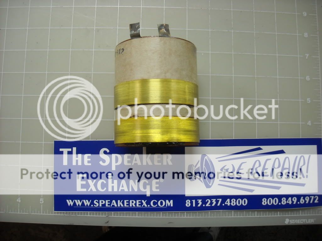
It has 0.8" WW as per the Speaker Exchange website where it is offered for sale (which is pretty obvious if you look at the ruled grid).
Speaker Exchange | JBL 2268 Voice Coil
...and here is the differential drive coil from a W12/W15 GTi mobile audio subwoofer.
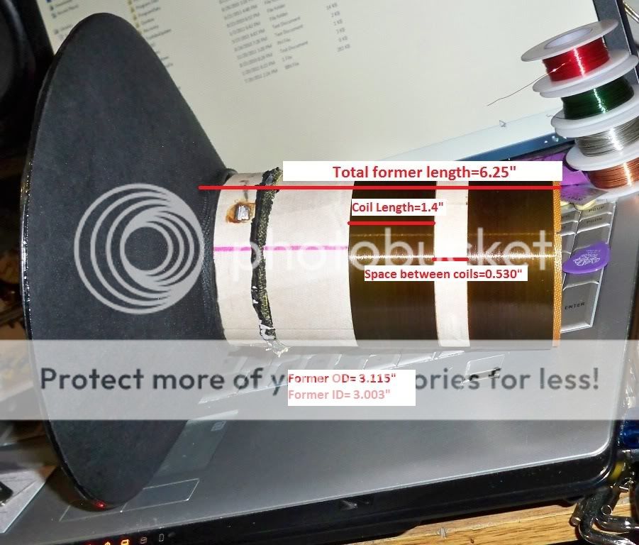
I guess there is really a point where the numbers have to make sense, assuming of course one is familiar with the topology of the magnetic circuit. So djk was clearly right all along; to get the true Xmax #s like the mobile audio WGTi series subwoofer, you need longer coils and longer spacing between the coils in a DDD magnetic circuit.
Perhaps it's time for some visuals:
Here is a pic of a 2268 differential drive coil:

It has 0.8" WW as per the Speaker Exchange website where it is offered for sale (which is pretty obvious if you look at the ruled grid).
Speaker Exchange | JBL 2268 Voice Coil
...and here is the differential drive coil from a W12/W15 GTi mobile audio subwoofer.
I guess there is really a point where the numbers have to make sense, assuming of course one is familiar with the topology of the magnetic circuit. So djk was clearly right all along; to get the true Xmax #s like the mobile audio WGTi series subwoofer, you need longer coils and longer spacing between the coils in a DDD magnetic circuit.
Last edited:
There is no doubt that one learns more by digging trougth parts than digging trougth brohures and spec files
I have a pair of 2243 baskets (same basket and motor as the 2242) here, and the pole piece protrudes 7mm above the top plate, probably one of the reasons why the Xmax can be larger than the winding heigth and the gap heigth suggests.
Anyway i guess i have no reason to doubt my estimation of reaching atleast 10mm linear Xmax when i recone them with aftermarket 2245 parts mated with a coil with a 27mm winding
- Status
- This old topic is closed. If you want to reopen this topic, contact a moderator using the "Report Post" button.
- Home
- Loudspeakers
- Subwoofers
- JBL 2268HPL as opossed to JBL2242H