Hi all.
Firstly my apologies for a lengthy post, but I'd like to explain where I'm going....
Basically, I wish to build a replica of one of the original horns as used in the Sensurround project - a horn capable of reproducing random noise centred around 15Hz at a high SPL.
So what was Sensurround?
For those of you who don't know, Sensurround was an audio enhancement to a few films released during the 70s, the idea being to create a subsonic rumble - typically around 15Hz - to heighten realism during action scenes in films such as
'Earthquake' by creating vibrations within the human body, but very little audible sound. I understand it was normal for 6 horns to be positioned around the auditorium - 1 in each corner, utilising the walls as an extension to the horn, and another two stand-alone units behind or to the sides of the screen. Cerwin-Vega were the company who designed the drivers and cabinets, but no longer have any information.
These horns were large, as you'd expect, and from what limited information I have were designated the 'W', 'C' and 'E' horns. It is the 'E' horn I wish to build as it appears to consist of 2 separate, and slightly smaller components.
Now why:
I am known locally as the 'guy who likes speakers', and this is why I was approached by a small local theatrical charity who have asked me for advice on constructing a device for creating subsonic rumble, as they wish to use Sensurround type effects during some of their presentations. The person concerned did go to see Earthquake in the 70s, as I did, and we both agreed this is the effect needed. Incidentally, normal subs don't do the job - we tried! It was also agreed that a close copy of one of the original units, both in construction and finish would be a good nostalgia trip for some, and this is what I ultimately wish to build.
Although the finished unit has to be portable to a degree, size isn't too much of an issue as it would remain in situ for weeks at a time and only be moved occasionally. Corner placement would be ideal.
Do any of you have copies of the original plans for these horns, including dimensions?
How would modern 18" drivers serve in these horns? (I have a pair of Fane Colossus 18B 600s available for this)
How about photos so I can see what they actually looked like?
Anyone in possession of one of these beasts? They had to end up somewhere, after all!
Many thanks for any help you can offer.
Andy.
Do a search on this forum for Magnetar.
He has three on his back wall. His fire downard and couple with the floor.
Here is a link that he posted...
http://www.in70mm.com/newsletter/2004/69/sensurround/images/horn_1.jpg
Hope this helps...
He has three on his back wall. His fire downard and couple with the floor.
Here is a link that he posted...
http://www.in70mm.com/newsletter/2004/69/sensurround/images/horn_1.jpg
Hope this helps...
Magnetar posted this picture of his three (model m) Sensurrounds
http://hometown.aol.com/batespm/images/bass.jpg
http://hometown.aol.com/batespm/images/bass.jpg
That's interesting.
They don't appear to be quite as the diagrams would suggest - I must assume this is a type not illustrated, which the 'M' type you gave them would suggest.
I'm wondering for the moment if they are original Sensurround units, or similar devices that Magnetar has built, and called 'sensuround' after the cinema models.
I've sent Magnetar a private message anyhow, outlining my query much as I've desctibed it in this thread, so hopefully he will enlighten us. Those horns certainly look the business, whatever they are!
Andy.
Magnetar is a quiet, gentle soul -- never one to speak his mind 
He has one of the finest horn rigs I have ever seen (and home-built).
Also, he loves HEIL AMTs (as I do).
Here is another of his posts -- an interior shot of one of his Sensurround Ms (beefed and modded for his 18" driver)
http://hometown.aol.com/batespm/images/admhrn.jpg
It bears a remarkable resemblance to the M-Type in the diagrams he posted (bottom-most right diagram)
Best Regards
I think I have my model numbers a bit mixed up - the model I'm interested in is the 'M' type, as you say it appears lower right on the diagram. Quite where I got 'E' type from, I'm not sure....
And yes, Magnetar's M horn is obviously based on the Sensurround original, or is an original he's modified, and it's this I wish to construct. Two of them.
As wood is reasonably cheap, and my free time is... um.... free, I'm going to build a pair for working into the corner of a large room, as intended for the originals. It's an unexplainable urge - I'm sure you guys can appreciate that!
Just need to study horn theory a bit more to make sure I'm not making any huge mistakes with the dimensions, and don't destroy expensive speakers through over-excursion.
Charles, thanks for your comment - what you suggest might do the trick but I feel I've gone too far down the horn route already - I'm developing a bit of a passion, you see......
Meanwhile, any more photos or specifications/dimensions of the original Sensurround horns will be very welcome, especially information on the original drivers used, and how they differed from what is available now.
Andy.
Hi all. An Aussie Sensurround freak here I saw all the Sensurround movies over and over in the Forum Cinema in George Street Sydney in the 1970s and I think one in about 1980 (Mission Galactica - The Cylon Attack which was bad). The effect was very audible indeed! There was allegedly infra-sonic content generated by the "pseudo random noise generator circuit" which fed the amplifiers and horns in the cinemas and this is probably the bit that you felt in your gut during the earthquake sequence of Earthquake. The original Cerwin Vega Sensurround horn cabinets used 18 inch model 189E drivers. The cabinets were pretty ugly black/grey painted plywood and they were not capable of response down to 15 Hz as stand-alone units. Many were put together side-by-side with plywood mouth extension boards to increase their effective mouth area across the front of the cinema to create a huge wavefront emanating into the theatre space. As well as these, some were coupled to the rear walls and used the theatre corners is a kind of extension of the horn mouth. I have built a couple of home cinema versions of the Model M (M actually stood for "modular" and had nothing to do with their shape) horns and use them at home. One is coupled to a corner and the other is coupled to a wall. I have a PDF file somewhere with dimensions of the original Model M horns which I stumbled across on the Internet some months ago, but I believe that the original sealed enclosure was too big as driver failures were apparently common. The 189E drivers must be mounted in a small sealed enclosure or they will fail. I recall reading somewhere on the Internet that even a small leakage in the side access panels would cause premature failure of the drivers. The drivers have a very small cone travel of around 6 mm. I was able to mount mine in a sealed box having a volume of a mere 1 cubic foot (about 30 litres). This necessitated a strange cabinet shape with many 45 degree cuts and an octagonal shape. 32 mm MDF was used for rigidity and weight. The sealed enclosure is buried deep in the folder horn structure. In my home set-up I drive the horns with a Cerwin-Vega "A-3000 I" power amplifier which is very similar to the "Model 3000" types originally specified and was marketed by Cerwin Vega in the day as an "Earth shaker" amplifier. It has about 350 W RMS into 8 ohms and something over 500 W into 4. The effect is quite phenomenal, but the house has suffered slipping roof tiles and plasterboard cracks as a result of my enthusiasm. On the recent DVD releases of the old Sensurround movies I would assume that the rumble content is pretty much the same as that generated by the original cinema noise generator circuits. My horns have a pretty big peak at around 50 Hz and much of the sound effects are concentrated around there. Sealed bass enclosures have a natural roll-off of the lower frequencies below resonance of 12 dB per octave and this is what feeds into the horn throat, so what I have done is build a dual integrated circuit "processor" to to feed LFE ".1" channel input to the power amplifier (a pair of op amps each provide 6 dB per octave boost - look at the Elliott Sound Products ESP web site for details). The problem is, at lower frequencies demands on the amplifier are much greater. For example without the processor I can feed the amplifier with a 1 Volt output of a sine wave oscillator and vary the frequency between say 115 Hz and 15 Hz and get a huge audible peak at around 50 Hz with the VU needles on the power amplifier staying at the same level irrespective of frequency. With the processor in circuit, the audible frequency response from the horns is pretty much flat right down to 20 Hz (where I deliberately rolled off the circuit as amplifier demands would have been utterly ridiculous down there!), but as the frequency is reduced on the oscillator, the VU needles on the power amplifier climb rapidly toward the red clipping zone and you don't want to go there! Of course my next project was to build a power limiting optical feedback circuit for the power amplifier per another one of the projects found on the ESP web site. This circuit takes the .1 channel and feeds it to the power amplifier, but is also connected to the speaker binding posts of the amplifier and illuminates an optical coupling device known as a Vactrol to vary the resistance in a light-dependent resistor to shunt excessive input to ground. It's like a feedback circuit on the power amplifier without a direct electrical coupling which would blow it up instantly. This is an awesome combination. Flat frequently response right down to the point where clipping would otherwise start but it doesn't. Instead the .1 program content is compressed and therefore still sounds loud just below the clipping . If there is any interest in what I have said here, I'll be happy to upload photographs of the horns taken during construction, the original Cerwin Vega speaker plans and other bits and pieces.
Cheers, Ian
I saw all the Sensurround movies over and over in the Forum Cinema in George Street Sydney in the 1970s and I think one in about 1980 (Mission Galactica - The Cylon Attack which was bad). The effect was very audible indeed! There was allegedly infra-sonic content generated by the "pseudo random noise generator circuit" which fed the amplifiers and horns in the cinemas and this is probably the bit that you felt in your gut during the earthquake sequence of Earthquake. The original Cerwin Vega Sensurround horn cabinets used 18 inch model 189E drivers. The cabinets were pretty ugly black/grey painted plywood and they were not capable of response down to 15 Hz as stand-alone units. Many were put together side-by-side with plywood mouth extension boards to increase their effective mouth area across the front of the cinema to create a huge wavefront emanating into the theatre space. As well as these, some were coupled to the rear walls and used the theatre corners is a kind of extension of the horn mouth. I have built a couple of home cinema versions of the Model M (M actually stood for "modular" and had nothing to do with their shape) horns and use them at home. One is coupled to a corner and the other is coupled to a wall. I have a PDF file somewhere with dimensions of the original Model M horns which I stumbled across on the Internet some months ago, but I believe that the original sealed enclosure was too big as driver failures were apparently common. The 189E drivers must be mounted in a small sealed enclosure or they will fail. I recall reading somewhere on the Internet that even a small leakage in the side access panels would cause premature failure of the drivers. The drivers have a very small cone travel of around 6 mm. I was able to mount mine in a sealed box having a volume of a mere 1 cubic foot (about 30 litres). This necessitated a strange cabinet shape with many 45 degree cuts and an octagonal shape. 32 mm MDF was used for rigidity and weight. The sealed enclosure is buried deep in the folder horn structure. In my home set-up I drive the horns with a Cerwin-Vega "A-3000 I" power amplifier which is very similar to the "Model 3000" types originally specified and was marketed by Cerwin Vega in the day as an "Earth shaker" amplifier. It has about 350 W RMS into 8 ohms and something over 500 W into 4. The effect is quite phenomenal, but the house has suffered slipping roof tiles and plasterboard cracks as a result of my enthusiasm. On the recent DVD releases of the old Sensurround movies I would assume that the rumble content is pretty much the same as that generated by the original cinema noise generator circuits. My horns have a pretty big peak at around 50 Hz and much of the sound effects are concentrated around there. Sealed bass enclosures have a natural roll-off of the lower frequencies below resonance of 12 dB per octave and this is what feeds into the horn throat, so what I have done is build a dual integrated circuit "processor" to to feed LFE ".1" channel input to the power amplifier (a pair of op amps each provide 6 dB per octave boost - look at the Elliott Sound Products ESP web site for details). The problem is, at lower frequencies demands on the amplifier are much greater. For example without the processor I can feed the amplifier with a 1 Volt output of a sine wave oscillator and vary the frequency between say 115 Hz and 15 Hz and get a huge audible peak at around 50 Hz with the VU needles on the power amplifier staying at the same level irrespective of frequency. With the processor in circuit, the audible frequency response from the horns is pretty much flat right down to 20 Hz (where I deliberately rolled off the circuit as amplifier demands would have been utterly ridiculous down there!), but as the frequency is reduced on the oscillator, the VU needles on the power amplifier climb rapidly toward the red clipping zone and you don't want to go there! Of course my next project was to build a power limiting optical feedback circuit for the power amplifier per another one of the projects found on the ESP web site. This circuit takes the .1 channel and feeds it to the power amplifier, but is also connected to the speaker binding posts of the amplifier and illuminates an optical coupling device known as a Vactrol to vary the resistance in a light-dependent resistor to shunt excessive input to ground. It's like a feedback circuit on the power amplifier without a direct electrical coupling which would blow it up instantly. This is an awesome combination. Flat frequently response right down to the point where clipping would otherwise start but it doesn't. Instead the .1 program content is compressed and therefore still sounds loud just below the clipping . If there is any interest in what I have said here, I'll be happy to upload photographs of the horns taken during construction, the original Cerwin Vega speaker plans and other bits and pieces.Cheers, Ian

Thanks Ian for a very informative post;
Since starting this thread I've learnt a few things about the Sensurround horns - for one, it is a pair of the model 'M' horns I wish to construct, and these would be stacked and operated into a corner as originally intended. The frequency response doesn't centre about 15 Hz as I originall thought; The signal consisted of frequencies in the octave or so above 15Hz, meaning sound between 15 or so up to 30 and probably higher.
I have also heard that the Cerwin-Vega drivers used to fail on regular occasions, but I'm wondering why - was it a mechanical failure due to over-excursion, or overheating? Builing a driver to accept 250 watts continuous (500 watts into 2 X 8 ohm drivers) was a bit of a problem in the '70s, after all.
Anyhow, I would indeed be very interested in any information you have, especially the PDF file you mentioned.
Thanks for replying.
Andy.
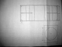
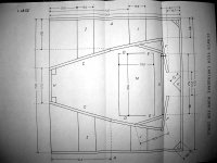
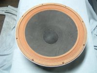
Hi Andy. As I am new here and under "observation", I cannot email you, so I will convert the PDF into JPG and post it here. Actually the drawings are for a cabinet for a 189ES driver which was similar. The 189E was an incredibly robust monster with sand cast basket, paper cone and linen/wax suspension surround. I will post a photo of one of mine here. I do not know the reason for failure, but guess its a travel thing. Cheers, Ian

I went and saw "Earthquake" in some cinema in Melbourne at the time, purely to hear the sound. Couldn't care less about the movie! Not long after, another movie Midway came along also using Sensurround. That was hopeless. Every time a bomb dropped there was an identical 50Hz blurt from the big speakers. Very monotonous.
Anyway, just before Earthquake hit the screens, Electronics Australia magazine ran an article telling all about the hardware used in the cinemas including IIRC drawings of the speaker boxes. They stated the 18" drivers used had a p/p movement of 1.5 inches and displaced about 300 cubic inches when doing so. No, I haven't got a copy of the article; that's from memory.
Anyway, just before Earthquake hit the screens, Electronics Australia magazine ran an article telling all about the hardware used in the cinemas including IIRC drawings of the speaker boxes. They stated the 18" drivers used had a p/p movement of 1.5 inches and displaced about 300 cubic inches when doing so. No, I haven't got a copy of the article; that's from memory.
Thanks Ian for the uploaded plans - I've saved the image for reference when I actually get around to cutting wood.
I've also heard about the rather large displacement these Cerwin Vega drivers were supposed to have, but I wonder what the Xmax was? I doubt the designers of the Sensurround system would have bothered about distortion or other non-linearities caused by moving the cones beyond this point, as hi-fi was unnecessary here - it was all about decibels.
I notice that the Precision Devices PD1850 has a maximum excursion limit of 1.26 inches, although whether that's peak to peak or one direction only I don't know; Quite a bit for a PA driver anyhow, Xmax rather less than this, obviously.
I have included a photograph showing the old-fashioned corrugated suspension of the 189 E driver. I suspect that the Xmax of 5.2 mm quoted by GM is accurate. The cone travel of the drivers as mounted in their sealed enclosures was quite small during a test in which I ran a portable CD player through the A-3000 I amp to the drivers while playing the opening track of the Varese Sarabande CD soundtrack from the 1977 Dracula movie (VSD-5250) which has amazing rumble content for testing purposes. The cones hardly moved but the crockery in the kitchen did and and that was without any horn loading! Actually I have a feeling that the use of a long throw speaker driver in a folded horn cabinet might create too much turbulence in the throat. I considered using more modern drivers but dismissed the idea given that the effect that I wish to achieve was to be as close as possible to real Sensurround. I will post a few more photographs in subsequent links for interest.
Ian
Ian
Attachments
- Status
- This old topic is closed. If you want to reopen this topic, contact a moderator using the "Report Post" button.
- Home
- Loudspeakers
- Subwoofers
- Sensurround horns - any information please?