I turned up the volume on the onkyo DR-S2.0 for about a minute and the Sub-woofer Onkyo SKW-30 stopped putting out sound. The red standby light is still on, but no sound. I tried touching the input cable to get some hum, but nothing. Before it failed, the green power light would flicker when there were bass sounds on the input.
Taking it apart, there is a burn mark on the pcb under a 29K power resistor. Trace burned. The resistor measures 20K, but the colors are red, white, orange. So I replaced it with a 29.6K 5W power resistor.
Still nothing. No sound, but red standby light is on.
I tried a 20K again, but nothing.
Anyone know what the typical problem is with the circuit/product?
Schematics?
thanks,
charlie
Figured a few things out.
First, there was a bad solder joint between the power supply module and the main board making the V- an open circuit. They just didn't have enough solder on it to bridge between the two circuit boards. Now, I get sound.
But, second, I found a resistor loose, rattling around inside the subwoofer case. It is identical to the resistor where the burn mark is on the pcb. It appears that at R16, there was a resistor on the top and bottom of the board in parallel. The bottom one fell off from the heat.
Now, the question is, both resistors are 1 watt with color codes Red, White, Orange. But they both measure 20K. Does anyone know what the value should be at R16 on an SKW-30 Onkyo 60W subwoofer? The colors are so vivid, that I cannot see how I could read them as 20K.
thanks again.
There is a Service bullitin for this model.
Have attached the service manual update schematic
Hope this helps
SKW-30 Symptom: No power at all Solution: In some instances the power supply block VCC input solder point may be cracked or detached from the main PCB solder terminal. The voltage through R16 may not arrive at its intended target should this happen causing unit not to operate. Make a jumper wire from one end of R16 as seen to the block solder terminal VCC point. Warning: When performing this procedure one must make sure unit is not plugged to the any power source and discharge power supply capacitors very slowly. Do not introduce instant discharge of the power supply filter capacitors, as it would harm the power block
Have attached the service manual update schematic
Hope this helps
Attachments
Glad you got some help. My unit is dead as well. I opened up the unit and saw a burn trace underneath my PCB and a burned up power resistor on top. I had no idea there was another resistor in parallel underneath.
Question: Did you just replace with one resistor only instead of using the parallel method? Just want to make sure what you did. I take it from the supplied schematic this what you do but not sure. BTW, what is the value of R76? Can't make this one out to well. It looks like 6K8?
Question: Did you just replace with one resistor only instead of using the parallel method? Just want to make sure what you did. I take it from the supplied schematic this what you do but not sure. BTW, what is the value of R76? Can't make this one out to well. It looks like 6K8?
mine is working fine for a month now
I replace r16, where the burn was with a 5 watt 13K metal oxide power resistor. I opted for the larger rating so it could run a bit cooler. I also mounted it so it didn't touch the board so air could get around it for cooling. I used the extra lead length sticking thru the board to go overtop the burned circuit board traces and ended up replacing the entire trace near the resistor with the wire. The copper around the resistor holes was completely burned away. I used a 13K (which measured 12.8K) because I had one. I originally got the resistors from www.mouser.com . digikey.com is another good source for parts if you don't have a local supplier. When mounting the part, consider that it will be subjected to lots of vibration, as the speaker is aimed right at the circuit board. Also, make sure to resolder the joints between the power module and the main pcb. You are trying to bridge solder between the foil on the two pcb's.
If you are going to do the parallel method, I would suggest using 2 or 3 watt 24K resistors.
Either case, you need to deal with remaking the copper connection, where the copper got burned.
For R76, 6K8 is a way of representing 6.8K ohms.
Attachments
Re: mine is working fine for a month now
Thanks you so much for your help. I will start this project tomorrow and hopefully have something good to report back.")
cm3 said:I replace r16, where the burn was with a 5 watt 13K metal oxide power resistor. I opted for the larger rating so it could run a bit cooler. I also mounted it so it didn't touch the board so air could get around it for cooling. I used the extra lead length sticking thru the board to go overtop the burned circuit board traces and ended up replacing the entire trace near the resistor with the wire. The copper around the resistor holes was completely burned away. I used a 13K (which measured 12.8K) because I had one. I originally got the resistors from www.mouser.com . digikey.com is another good source for parts if you don't have a local supplier. When mounting the part, consider that it will be subjected to lots of vibration, as the speaker is aimed right at the circuit board. Also, make sure to resolder the joints between the power module and the main pcb. You are trying to bridge solder between the foil on the two pcb's.
If you are going to do the parallel method, I would suggest using 2 or 3 watt 24K resistors.
Either case, you need to deal with remaking the copper connection, where the copper got burned.
For R76, 6K8 is a way of representing 6.8K ohms.
Thanks you so much for your help. I will start this project tomorrow and hopefully have something good to report back.
I have been trying to repair anSKW-30 subwoofer for my nephew. I removed the ckt board and notice a scorch mark under the M3 module between V= and V-. The resistance between Vcc and V- is 1 ohm (pretty much a short) and Vcc to V+ is 132 ohms. This module is filled with a black epoxy resin so I can't troubleshoot it any further.
Here's my questions:
Does this module supply a variable output?
What is the voltage at P and N of this module?
Can I substitute an external power supply and not worry about burning down the neighborhood?
Thanks in advance. I look forward to your responses with great anticipation.
Here's my questions:
Does this module supply a variable output?
What is the voltage at P and N of this module?
Can I substitute an external power supply and not worry about burning down the neighborhood?
Thanks in advance. I look forward to your responses with great anticipation.
Here is some useful information I received from Onkyo.
Parts ordering direct:1-800-229-1687 option 5 on the menu.
Parts breakdown and pricing for subwoofer SKW-30:
1) 1216SKW30 M10GA FREQUENCY SELECTOR KNOB SKW30 $2.50
2) 283-12K S45HB 12K OHM 3W RESISTOR SKW30 $1.25
3) 511SKW30 M10GA VOLUME KNOB SKW30 $2.50
4) EAC3M1C RCA CABLE SKW30 $3.00
5) EAMOSKW30 S13C AMPLIFIER PCB SKW30 $123.00
6) EAMOSKW30-1 S15B VOLTAGE BLOCK SKW30 $25.00
7) EAMOSKW30P R61B PRE-AMP W/HARNESS + VOLUME CTR SKW30 $28.00
8) ELP2219 S45FB +/- LEAD SET SKW30 $2.25
9) EWF61615P R10B EWF61615P WOOFER SKW30 $22.75
10) EWF6I615P 240E EWF61615P WOOFER SKW30 $22.75
11) LM3876TF-ND S24FB IC SKW30 $20.33
12) SKF110W 304A7 FUSE AGC 2A 250V SK10W SK10W $1.00
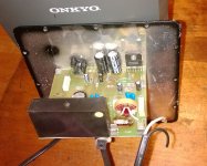
This resistor?
If I understand correctly, I could replace the burned up resister in this picture with 5 watt 13K metal oxide power resistor and be back in business?
I see the part# 286 on this spec sheet here on Mouser Electronics - Electronic Components Distributor matches that.
If I understand correctly, I could replace the burned up resister in this picture with 5 watt 13K metal oxide power resistor and be back in business?
I see the part# 286 on this spec sheet here on Mouser Electronics - Electronic Components Distributor matches that.
Eff it
Whole damn thing went to shite. Burned my finger pretty good with my soldering iron. Situation normal. Most of my problem was not understanding the performance difference when your soldering iron isn't tinned properly. Anyhow, it's a tough resistor to get to, in my humble opinion, for the other DIY jack of all trade types out there looking at this specific issue.
Me and my craigslist $75 4 years ago Onkyo 5.1 system are happily thumping away with a Pioneer SW-8MK2 I got on sale at Best Buy for $99 a week ago. I'll start yearning for better sound soon, however.
Game over and game on. In the process I found a new local electronic component supplier called Vetco with helpful and knowledgeable counter guy. Totally cool.
- Status
- This old topic is closed. If you want to reopen this topic, contact a moderator using the "Report Post" button.
- Home
- Loudspeakers
- Subwoofers
- Onkyo subwoofer skw-30, repair help needed