in an effort to produce the ultimate subwoofer with huge excursion, very low FS for HT use... and tons of output off of little power to around 10hz (looking for on the order of 120db at 10hz with this in dipole) I've come upon geo's rotary sub
http://www.betteraudio.com/geolemon/servoproject/
the idea is awesome and would easy produce massive stable excursion, very low fs if you wish and probably could be made to work well in dipole")
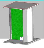
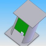
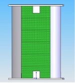
so I modeled this up in CAD tell me what ya think
the Kevlar panel in the cylinder is 25" wide and would be within .1" to the sides of the cylinder...
the panel is also 40" tall... so around 12x40 effective cone area if I understand this design correctly....
http://www.betteraudio.com/geolemon/servoproject/
the idea is awesome and would easy produce massive stable excursion, very low fs if you wish and probably could be made to work well in dipole
so I modeled this up in CAD tell me what ya think
the Kevlar panel in the cylinder is 25" wide and would be within .1" to the sides of the cylinder...
the panel is also 40" tall... so around 12x40 effective cone area if I understand this design correctly....
Attachments
maybe we'll see
I was trying to model specs in BB6... granted it's questionable trying to get a rotary's specs from a pistonic program
but ideally I want a 7hz Fs with this design, around 3000cm2 of Sd, as much Xmax as I can get, Mms around 2000g, CMS <.25mm/N and BL below 14 N/A.... I guess this would be applying this to a pistonic speaker... so I dunno about this design
I'm looking for a QTS of around .9 and a Fs around 7hz I guess those are the only true specs I care about
I was trying to model specs in BB6... granted it's questionable trying to get a rotary's specs from a pistonic program
but ideally I want a 7hz Fs with this design, around 3000cm2 of Sd, as much Xmax as I can get, Mms around 2000g, CMS <.25mm/N and BL below 14 N/A.... I guess this would be applying this to a pistonic speaker... so I dunno about this design
I'm looking for a QTS of around .9 and a Fs around 7hz
I guess those are the only true specs I care aboutrealistically a QTS around .9, Fs around 15hz and MMs at least 1000g is all that I want as far as specs (Mms is the least I think I can get while keeping a very strong cone)....
I dunno about everything else... it seems a very low Cms is needed to do this.... below 0.1 mm/N...
I dunno about everything else... it seems a very low Cms is needed to do this.... below 0.1 mm/N...
Have you got suitable servo drives for the motors? It seems a very expensive way of doing it, but interesting. I wonder what would happen if I fed an audio signal into our test servo drive at work; would it be happy to go back and forward rapidly for fractions of a revolution. It uses an optical encoder for positional feedback, and this works at all speeds, but I'm not sure how it would react to an audio signal over fractions of a revolution.
I'm sure I saw an ad for a system that used a servo controlled fan to move lots of air at low frequencies, but I forget details about it; maybe it's the one you described.

I'm sure I saw an ad for a system that used a servo controlled fan to move lots of air at low frequencies, but I forget details about it; maybe it's the one you described.
i think you should throw something together out of cardboard just to see how it all works, then worry about the fine details.
so the concept is that you hook up an AC signal from an amp to a servo motor and it turns in frequency with the signal? but it needs a "return" mechanism to make it pulse, otherwise it just turns in one direction?
so the concept is that you hook up an AC signal from an amp to a servo motor and it turns in frequency with the signal? but it needs a "return" mechanism to make it pulse, otherwise it just turns in one direction?
johnnyx said:Have you got suitable servo drives for the motors? It seems a very expensive way of doing it, but interesting. I wonder what would happen if I fed an audio signal into our test servo drive at work; would it be happy to go back and forward rapidly for fractions of a revolution. It uses an optical encoder for positional feedback, and this works at all speeds, but I'm not sure how it would react to an audio signal over fractions of a revolution.
I'm sure I saw an ad for a system that used a servo controlled fan to move lots of air at low frequencies, but I forget details about it; maybe it's the one you described.
no different design... basically what happens is the motor tries to spin the the kevlar panel but the tortion bar (not very stiff) sends it back to rest position... I know the fan you're talking about though
I need to know how much BL the design can stand so I can choose the motor strength... a design I'm quite happy with has a BL around 30 N/A... but this is in BB6
but I would like really efficent motors... which is basically what a servo motor is... it's not really as expensive as you think.... maybe for a huge 1.5 HP monster it would be... but not this design me thinks
~cownrg
that's the tortion steel mechanism Geo designed... it would work quite well as a suspension and allow you to fully control the suspension stiffness by steel thickness and/or adjusting distances of the pads...
it's like the last pictures on the page
I believe the idea is two servo motors...
one side of the cone would always be going forward and to rest position and the other side would always be going back and to rest position...
at least this is the only way that makes sense... it's a bipolar speaker in theory
hum. so, would you invert the signal coming into each motor?
im just not understanding how it works...
it sounds like the motors are just spinning a fraction of a revolution, then being pulled back by a spring or tension. but they do this at X/sec for the frequency of the audio signal.
so its a vane of material that flutters back and forth along a rotational plane rather than a through a plane, like a piston...
BUT, how do you send this information to the motors? will a simple AC signal be enough to turn the motors?
cowanrg said:
BUT, how do you send this information to the motors? will a simple AC signal be enough to turn the motors?
yes the run off dc... I'm reading up on geo's site and I think the concept is sending the full AC signal... and on + signals they excurt out and to rest and then on the - signal it goes backward just like a piston
I don't think this design can extend much beyond say 50hz... maybe I'm going about this the wrong way..... I dunno...
if I could find a 24" surround that could do over 3-5" one way and a spider that can also do that...
this seems easier to me though... and probably will be cheaper
cowanrg said:hum, in that case, why would you need the return mechanism...
i have many servos in the basement, maybe ill hook a couple up to an audio AC signal and see what happens...
well the idea is that you want the rest position so you don't get these MAD swings and can keep it in the area you want... sure the compliance is very low in most cases but it's necessary ....
if you don't have a return position if you get a transient of bass you will get gawd awful IMD...
I dropped the rotary idea to try for a normal cone speaker with fully custom everything... suspension will still be like that though
the design I'm thinking about is a 27" diameter real conical subwoofer and a gear/chain system that will transfer the power into linear output... looking to try for around 5" one way and it doesn't seem too far off in reality...
I'm trying to decide if a real servo motor or rotary like geo's would be best and for space without a doubt the IB 27" would do it
I have a design mocked up that will work as long as I can get suspension right....
a 27"-30" with 200mm one way would be equal to around 16 of the New 18" XXX's in output (the new 50mm one way ones)... and it's way more efficent... (WAAAAY)
I drew up the gear design in CAD and the box is around 27" tall and a tube 27-30" wide... this should easily fit the woofer and allow for this excursion... it will be firing down and the cone will be made out of alum or a kevlar mdf composite and weigh around 4 lbs
aiming for a QTS around .9 to allow the magnitude of bass in a dipole system...
questions to have answered:
1. did you use AC or DC motors? DC seems like the only way to make it work
2. can you give me the model number for the servos you used?
Hi
Oh, I don’t know about that, I don’t think alone exactly.
Rotary systems have a different set of rules than “in and out” systems.
The effect of mass on a rotary speaker is VERY strongly dependent on where it is in relation to the axis of rotation.
A rotary motor (DC serovomotor) has a torque constant, KT, this is in units of force per amp.
This is normally (for a small motor like this) this torque is specified at a one inch radius (here in the states) with one Amp of current.
If one used a ½ inch diameter shaft to drive the radiator, then, one has the “load” connected at a ¼ inch radius and by the principal of mechanical advantage, has the effect of 4 times the force of KT.
Force to load per Amp = KT / Radius of mechanical conversion.
Once that torque is converted to linear motion, that force per amp becomes the BL product. A drivers actual motor strength is proportional to (my preferred) BL /sqr root of Rdc which is a figure that is Newton’s of force per Watt of motor dissipation, or BL^2 /Rdc as a figure of merit.
A rotary system has a moment of inertia, this is different than mass.
This is given as Jm, in a weird unit which includes acceleration of gravity.
That would be a unit which includes force, radius and acceleration.
The blue Pac-Sci motor shown in the Cyclone pix has a Jm of .00074 oz/in/sec^2
And a KT of 9.1 oz/in per Amp and Rdc of .89 Ohms for example.
Take the same motor as before with the ½ inch drive shaft. What ever its Jm was, the effective mass that represents is proportional to Jm / Radius of conversion squared
While having a ½ inch radius increases the effective BL by 4, it also increases the motors effective mass by 16 times.
As you can see, changing the shaft diameter has a large impact on the Thiel Small parameters you end up with.
If you want to do a reality check, here are the Driver parameters for a Contrabass.
That motor (similar to the little blue one) has a KT = 14.1 oz/in/amp Rdc =1.9 Ohms Jm = .00074 oz/in/sec^2.
Rdc=1.9 Ohms
Le = .05 Mhy (very low)
Fs =19.4 Hz
Qm = 12
Qe = .23
Mms 960 Gms (a little more than half is the motor as I recall)
Vas = 287 L
Sd 1710.6 cm^2
Xmax = Xmech = 40mm P/P
Thermal time constant ~ 45 seconds (about 10 seconds for a big VC)
Anyway, the thing is, since you dealing with an existing motor (the first servodrive was made with a motor I got at a junk store), you kind of have to pick some radiator values and go through the math to find out where you are and which way to go.
See, your not alone.
Have fun
Tom Danley
Danley Sound labs
PS, don’t bother with chain or belts with teeth, they all make too much noise, use flat thin drive belts. Thin because bending around the shaft they don’t flex to death and have a lot of losses. Do a search on Flat high speed drive belts, get familiar with what they look like then search out the surplus places like C&H sales etc. You do not want stretchy belts.
Also, the “Cyclone” approach works well but fabrication of the radiators is not simple given they need internal damping, low mass and to be stiff.
The approach is suited for a large back volume and not high back pressures unless you have really small gaps.
While the DIY’r can make the moving parts a bit too large and then slip thin sand paper between the stationary and moving parts, to sand the moving bit to size, it is not a “production method” (hint) but gives reasonably small clearances..
Tom Danley said:Hi
Oh, I don’t know about that, I don’t think alone exactly.
Rotary systems have a different set of rules than “in and out” systems.
The effect of mass on a rotary speaker is VERY strongly dependent on where it is in relation to the axis of rotation.
A rotary motor (DC serovomotor) has a torque constant, KT, this is in units of force per amp.
This is normally (for a small motor like this) this torque is specified at a one inch radius (here in the states) with one Amp of current.
If one used a ½ inch diameter shaft to drive the radiator, then, one has the “load” connected at a ¼ inch radius and by the principal of mechanical advantage, has the effect of 4 times the force of KT.
Force to load per Amp = KT / Radius of mechanical conversion.
Once that torque is converted to linear motion, that force per amp becomes the BL product. A drivers actual motor strength is proportional to (my preferred) BL /sqr root of Rdc which is a figure that is Newton’s of force per Watt of motor dissipation, or BL^2 /Rdc as a figure of merit.
A rotary system has a moment of inertia, this is different than mass.
This is given as Jm, in a weird unit which includes acceleration of gravity.
That would be a unit which includes force, radius and acceleration.
The blue Pac-Sci motor shown in the Cyclone pix has a Jm of .00074 oz/in/sec^2
And a KT of 9.1 oz/in per Amp and Rdc of .89 Ohms for example.
Take the same motor as before with the ½ inch drive shaft. What ever its Jm was, the effective mass that represents is proportional to Jm / Radius of conversion squared
While having a ½ inch radius increases the effective BL by 4, it also increases the motors effective mass by 16 times.
As you can see, changing the shaft diameter has a large impact on the Thiel Small parameters you end up with.
If you want to do a reality check, here are the Driver parameters for a Contrabass.
That motor (similar to the little blue one) has a KT = 14.1 oz/in/amp Rdc =1.9 Ohms Jm = .00074 oz/in/sec^2.
Rdc=1.9 Ohms
Le = .05 Mhy (very low)
Fs =19.4 Hz
Qm = 12
Qe = .23
Mms 960 Gms (a little more than half is the motor as I recall)
Vas = 287 L
Sd 1710.6 cm^2
Xmax = Xmech = 40mm P/P
Thermal time constant ~ 45 seconds (about 10 seconds for a big VC)
Anyway, the thing is, since you dealing with an existing motor (the first servodrive was made with a motor I got at a junk store), you kind of have to pick some radiator values and go through the math to find out where you are and which way to go.
See, your not alone.
Have fun
Tom Danley
Danley Sound labs
PS, don’t bother with chain or belts with teeth, they all make too much noise, use flat thin drive belts. Thin because bending around the shaft they don’t flex to death and have a lot of losses. Do a search on Flat high speed drive belts, get familiar with what they look like then search out the surplus places like C&H sales etc. You do not want stretchy belts.
Also, the “Cyclone” approach works well but fabrication of the radiators is not simple given they need internal damping, low mass and to be stiff.
The approach is suited for a large back volume and not high back pressures unless you have really small gaps.
While the DIY’r can make the moving parts a bit too large and then slip thin sand paper between the stationary and moving parts, to sand the moving bit to size, it is not a “production method” (hint) but gives reasonably small clearances..
You're the man tom... now if you would only send me info to build your unity horn
awesome let me digest that while I try to find the correct motor
structure... I'm not certain which is easier to follow geo's design using foam for that internal dampening or try to do a belt drive "pistonic" type of setup
to make the size of driver I'm wanting with that excursion I think doing something like "half" of geo's design...
I think it'll probably be easier for the first design attempt
- Status
- This old topic is closed. If you want to reopen this topic, contact a moderator using the "Report Post" button.
- Home
- Loudspeakers
- Subwoofers
- Servo rotary subwoofer!