Thanks John
Now that I got the stats what was your layout idea again. I know that it is hard to paint a picture with words. But are you trying to model the horn with the woofers in a manifold or multiple segment or what???
Tough question but if I get your drift I will be infor some awesome bass.
Mark
Now that I got the stats what was your layout idea again. I know that it is hard to paint a picture with words. But are you trying to model the horn with the woofers in a manifold or multiple segment or what???
Tough question but if I get your drift I will be infor some awesome bass.
Mark
Hezz,
I forgot to answer your HornResp question. For multiple drivers you enter a single driver's info. Just double click on parameters that you don't know and fill in the answers. You need the basics of Sd (I guesstimated 177 for the pioneer) Fs, Re, Qes, Qms.
Once you have one driver in, save that, then ADD to start a new model and make the multiple drivers. One driver won't do much in a short horn like this, but when you essentially stack 8 of them together, the results gets impressive.
I usually let it calculate an optimum hypex horn to see the potential and go from there. Figure out how to build it after you get the results you want.
One last thing- Parts Express showed and xmax of .10mm on that driver. I'm sure that must be a typo. I figured it was supposed to be 10mm. You might check with PE first before buying.
Re: Thanks John
The drivers would just be in a straight line below the one shown. Now that I think about it I'd alternate which direction each driver faces to get the extra benefit of push/pull operation. Get the wiring right if you do that. That would also give you double the air volume for temperature management if you plan to really push them.
mwmkravchenko said:Now that I got the stats what was your layout idea again. I know that it is hard to paint a picture with words. But are you trying to model the horn with the woofers in a manifold or multiple segment or what???
Tough question but if I get your drift I will be infor some awesome bass.
Mark
The drivers would just be in a straight line below the one shown. Now that I think about it I'd alternate which direction each driver faces to get the extra benefit of push/pull operation. Get the wiring right if you do that. That would also give you double the air volume for temperature management if you plan to really push them.

A Modeling I go yupp Yupp
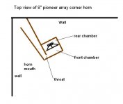
I thankyou for that drawing. I had seen something similar years ago and your pic triggered the memory. An ingenious use of the corner and big saving in cabinet volume and size. HornResp is up and running. I should have something modeled as soon as I can find the damn driver specs.
Greatly appreciate the reminder.
Mark
It's not really the right driver for going really deep. But if you can handle a 6ft tall 10"x10" rectangular box in the middle of your wall and only a 20" wide mouth in the corner, then those drivers will give you 110db flat from 45hz to 300hz on 1 watt and still have 100db at 22hz. Not bad for $170 worth of drivers, a few sheets of plywood and some wall and corner space. Arrays are powerful animals and if you throw horn loading into the mix it just gets crazy.
Re: A Modeling I go yupp Yupp
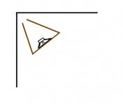
No problem Mark. With larger drivers you'd probably want to do a 4 segment horn with the folds behind the chamber. That way you can get much more horn length but retain a compact size. A super easy one with large drivers would look like this from the top.
mwmkravchenko said:I thankyou for that drawing. I had seen something similar years ago and your pic triggered the memory. An ingenious use of the corner and big saving in cabinet volume and size. HornResp is up and running. I should have something modeled as soon as I can find the damn driver specs.
Greatly appreciate the reminder.
Mark
No problem Mark. With larger drivers you'd probably want to do a 4 segment horn with the folds behind the chamber. That way you can get much more horn length but retain a compact size. A super easy one with large drivers would look like this from the top.
Attachments
Bingo
I'd better go to bed soon!
Ok John your last post is pretty much what I had in mind after looking at your first drawing. It's falling into the great minds think alike category. I'll need about a month because of contract commitments for April. Work always gets in the way of fun. But come May I'm gonna be a rocking and a rolling. I'd think that 7' would be a good height and make the cabinet no wider than 32" so that you can get it out the door. The folds and the transistion to the wall mouth interface will take a bit of head scratching but what the heck. It's a hobby. And I like good clean bass. With the right EQ this puppy could be flat to 32' pipe range. (Organ nut speak )
Night Night
I dream of woofers and horns or is it horny woofers?
Mark
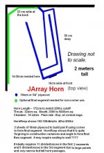
Using 3ftX3ft of corner space and an array of larger woofers you could probably get flat in room response lower than 32hz without EQ. About 2.5m of horn length should do the trick. I think I would build the final fold into the unit and not have to worry so much about attaching and sealing. Leave a little extra space on the rear right side, so you can turn the horn some to adjust the final flare and mouth. The really nice thing about the design is that folding isn't restricted to a rectangle making that part pretty simple. If you play with it in hornresp you'll see you have a lot of leeway in the segment lengths to make it all fit. Use a good number of pathway dividers which will act as braces to and it will be really solid and heavy.
For a 7ft tall one I would run the first 2 horn segments as 8 passages and 4 passages on the 3rd segment. I think this would be accomplished best with just 7 horizontal braces, 3 running the entire length and the other 4 just the first 2 segments. The 3 larger braces would look just like the pathway view from the top looking down. Make 1 and it would be the template for all of the other braces. Once you glue the braces to one panel, it would form a skeleton for the entire horn and make construction pretty straight forward. Just plan well the order you assemble it so you can seal it properly as you go.
Sorry about the lengthy explanation but I've already been through the planning of the 16 small driver horn, which starts with very narrow pathways making 15 divider/braces necessary through the 1st 2 segments with 7 of those through the 3rd segment in order to maintain a good height/width ratio of the pathways. I just need to decide on drivers.
John your priceless
If only you were a little closer than Costa Rica. I'd happily whip up your cabinet design. I appreciate your description. My background trade training is in cabinetmaking. Twenty years worth of stuff that did not include to many kitchens. Mostly furniture and fancy architectural millwork. Lots of curved work, bent mouldings, spiral staircases and the like. And I have done quite a few horns.
I had been working on a horn array off and on for about a year. But I could never come up with a reasonable cabinet that didn't require being built inside a house. They wouldn't fit through the door!
Then along comes John and bingo!
The lights are on again!
You do impress me with your forthought with regards to panel dampening. Right on the money. I woke up this morning with sort of the same idea but your idea will be better. If you think about it a bit you can trade the weight for proper panel stiffness. For example if you use 1/2" or 12mm material the stiffening ribs that you describe will allow a very stiff yet light cabinet. The ribs would have to follow the entire flow path to be effective at that panel thickness. I'm currently looking for poplar plywood with the same structure as Baltic birch. I know that it exists here in Ottawa I've worked on jobs were I saw it hanging around. It's just finding the right source for it. This stuff is very stiff and very light. (compared to birch) And is available in 4' by 8' sheets. It is easier to work with due to it's size and weight. And it is almost as stable.
For the horn bends there is some wonderfull stuff called bendable plywood that has become my favorite thing to use. It allows a pretty tight radius and when laminated up from two thinner sections ( 2 x 5/16" or 8mm = 16mm or 5/8") Makes for a very stiff wall. And it is not to expensive. At around $56 a sheet. I have a couple in stock but for these babys I will need around 8 or ten sheets.
Now to go and dig out the specs for the drivers.
I think I have some tea first. Specs are on my nose and off to the dungeon ( basement )
MArk
Thanks Mark,
It wasn't so much the panel damping that I was concerned about. It was keeping a ratio of less than 7/1 throughout the horn pathways and then how to build it. The throat on my small driver version is about 1/3 the size of this one for 8's, so virtually no way to get a hand in the 1st 2 horn segments once the panels are on. It could be all 12mm ply except the outer panel on the last segment.
Also, you don't have to worry about smooth curves at the bends with bass, so that makes everything really easy except making the braces and the driver holes and not much in the way of angles.
Plugging away
John I used hornresponse last about 6 months ago. I used to be able to print up a cm by cm area chart. I can't seem to figure out where that feature is now.
The preliminary findings with 4 15" drivers with a paltry 90 db efficiency. Series parallel configuration to 8 ohms I get 105 db per 2.83 volts or 1 watt 20 watts gets into the oh s******* category. That's good to 16 hz with a 50 square foot mouth. Allready designed a box with a book case on the larger flare wing portion to make some practical use of the beast. Also will provide a good mass loading. Oh the possibilities. MUHHAHAHAHAHHAH Look out neighbors!
Mark
P.S. 32' (or 32 foot) pipe length on an organ speaks at around 16 hz. If you have never heard it live it is hard to explain. But moving would be a start.
How do you post those nice pics? I have never been able to figure out how to do that.
Hold the presses. I found an error in the HornResp input for those pioneers. VRC is liters and VTC is CC's. For the response I was talking about, it needs to be a rear horn until I work some more on the design.
Mark, if you are plugging this stuff in be aware of that difference above. To see a schematic of your horn, do calculate then under "Window" the schematic is a selection item.
Mark, if you are plugging this stuff in be aware of that difference above. To see a schematic of your horn, do calculate then under "Window" the schematic is a selection item.
It's also about what I have on hand
Hi John.
Yes it is true about the 8's verses the 15's surface area is hard to beat.
The statement about the horn not needing rounded corners is true to a great extend. But one with curves looks so much more cool. And neat trick of good engineering or not. These horns will command the room. If you can't shrink them anymore than make them blend in. I have a really custom kitchen job coming up that is using black cherry. I see something in the works.
MArk
- Status
- This old topic is closed. If you want to reopen this topic, contact a moderator using the "Report Post" button.
- Home
- Loudspeakers
- Subwoofers
- Line array corner sub