Thank you for your attention....
At first i tryed a little with frequecy compensation. In som respekt better than without, but in other, well why not using that .
I'm looking for somthing sounds good and different (!)
So i found that the upper or mid range of a speaker sounded better with current drive, the bass behavior however was not satisfying at all.
High feedback near zero output impedance sounded good most of the time, but not always and the upper region was way down in my prefrences.
So given current compensation, we can compensate and we can even overcompensate.
I want The best of bouth, abt -3dB over all , -6dB in the upper region starting at (f=-3dB) and a tiny current compensation that boost current in the lower end (+)6dB all with the respect to my drivers Rdc and starting at box rolloff.
In a box with critical Q = 0.5 the slope is constant in a region and so is the other.
And the amp without load acts and has normal gain freq responce.
How far is it from North pole to reality ?
Hey Dude!
There's nothing impossible. The only limiting factor is space, and,
money.
It would be better to just state what you got, what you want, and, how much your willing to invest in the project.
What you got = Amplifier Power
What you want = Frequency Desired
How Much You're Willing To Invest = (I don't understand)
If you are limited in space, then, that puts a whole new look on your project.
Rock On !
There's nothing impossible. The only limiting factor is space, and,
money.
It would be better to just state what you got, what you want, and, how much your willing to invest in the project.
What you got = Amplifier Power
What you want = Frequency Desired
How Much You're Willing To Invest =
(I don't understand) If you are limited in space, then, that puts a whole new look on your project.
Rock On !
After a litle strugling on the subjekt compensation. I figured go for it!
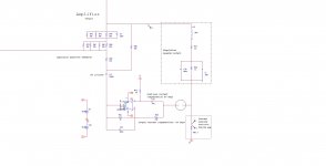
So as a starting point i simply started with a linkwist greiner. after a test i got the idea why not make the greiner current copled in a feedback loop.
Linkwist greiner current copled, i had to modify it a little.
Splitting it into positive and negative feedback did part of the trick.
giving it gain -1 for dc.
Resistive part of the load Rl (3.4 Ohm) and measuring resistor Rm (0.1 Ohm) (Rm/Rl =34) must slightly higher than the amplifiers negative gain. Amps gain = 34, negative gain 33 and you are almost safe as the output impedance is then -3.3 ohm. ie lower than zero output impedance in the werry verry (?) low end. ie if the load impedance was 16 Ohm the current thru would bee as if the load vas 12.7 Ohm. And if the output impedance was -3.4 Ohm ie a 3.4 Ohm load would act like short circuit ( dont try as maksimum output voltage is the result).
Now lets talk damping factor
Remember DC rolloff as any dc offset is amplifyed if not.
For the high end i did let the gain on a 3.4 resistor drop to a gain of 10 instead of 34.
simulating the know new current greiner with same corner and rollofs it matches the freq response of a external linkwits greiner. However simulating with a speaker model makes things a lot more interesting espesially considering delayed responces !
My Q is how abt temperature tracking on Rm ? is satisfying saying it is relatively lower than on Rl hence stable?
- Status
- This old topic is closed. If you want to reopen this topic, contact a moderator using the "Report Post" button.