Hi all,
I have come across the design and would like construct one, but I'm having trouble with the design plans. Here is a link:
LAB 15 - Speakerplans.com Forums
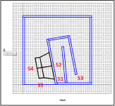
There are two diagrams, which I've attempted to recreate in SketchUp.
The biggest problem I'm having is the placement of the one individual panel that sticks out above the panel the driver is mounted to. The numbers imply it is nearly flat, horizontally, but apparently the angle is greater.
I've looked around a lot and would really love to get my numbers right.
Also, this version is built of a combination of 18mm an 15mm wood.
My goal is to make a plan that is about the same using all 18mm wood, and broken down into imperial units, panel for panel.
If anyone is willing to help out with this, I'm sure a lot of people would appreciate it, as it is a pretty compact, low extension TH, and I already have one of the drivers laying around")
Cheers!
I have come across the design and would like construct one, but I'm having trouble with the design plans. Here is a link:
LAB 15 - Speakerplans.com Forums
There are two diagrams, which I've attempted to recreate in SketchUp.
The biggest problem I'm having is the placement of the one individual panel that sticks out above the panel the driver is mounted to. The numbers imply it is nearly flat, horizontally, but apparently the angle is greater.
I've looked around a lot and would really love to get my numbers right.
Also, this version is built of a combination of 18mm an 15mm wood.
My goal is to make a plan that is about the same using all 18mm wood, and broken down into imperial units, panel for panel.
If anyone is willing to help out with this, I'm sure a lot of people would appreciate it, as it is a pretty compact, low extension TH, and I already have one of the drivers laying around
Cheers!
It looks like an MTH30 type of fold, which would require that horizontal panel be orthogonal to the panel that it's attached to. Based on the layout though ,it looks like the panel has to be angled about 1/3rd of the angle of the baffle panel for the driver, and this should be the same angle used for all of the other internal panels, which means that the bend at the top should have the panels joined at a right angle, not like how it's displayed in the section picture. That's just a guess though.
This is is something that I'd normally leave up to one of my workbook to work out.
When I have enough time, I'll check to see if my MTH workbook can be altered to support a dual expansion TH like that one.
This is is something that I'd normally leave up to one of my workbook to work out
. When I have enough time, I'll check to see if my MTH workbook can be altered to support a dual expansion TH like that one.
It looks like an MTH30 type of fold, which would require that horizontal panel be orthogonal to the panel that it's attached to. Based on the layout though ,it looks like the panel has to be angled about 1/3rd of the angle of the baffle panel for the driver, and this should be the same angle used for all of the other internal panels, which means that the bend at the top should have the panels joined at a right angle, not like how it's displayed in the section picture. That's just a guess though.
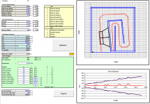
Turns out my guess was wrong. The only way this appears to work with a smooth expansion is if the panel next to the driver is at an angle that's 1/2 that of the driver's baffle panel. Also, the three internal panels that are connected together (starting with the baffle) should be at right angles to each other. Only then can it be sim'd via Hornresp (see attachment). No, it's not optimized - I haven't finished that part of the workbook yet
This "dual fold" MTH30 layout does result however in a larger mouth and shorter path than the standard MTH30 layout though. The end result should be a narrower passband and higher cutoff frequency. Anyway, I'll finish up the workbook to see what it comes up with for the external dimensions of that 40 Hz TH design at the link you provided.
Attachments
Thanks Brian! I'm a big fan of your page. I do recall it being said that one of the tapers is actually slightly negative.
My main goals here are to use the Lab 15 in a TH that doesn't start rolling off too high. Extension is the main goal, but supposedly the efficiency is pretty good too.
The other requirements are to use all 18mm birch and break down the plans into imperial units.
My main goals here are to use the Lab 15 in a TH that doesn't start rolling off too high. Extension is the main goal, but supposedly the efficiency is pretty good too.
The other requirements are to use all 18mm birch and break down the plans into imperial units.
Turns out my guess was wrong. The only way this appears to work with a smooth expansion is if the panel next to the driver is at an angle that's 1/2 that of the driver's baffle panel.
Well nope, that doesn't work either. Trying to get a dual-expansion working with that type of fold ends up with negative expansion, which is probably something to be avoided. Seems the only way this fold "works" is with a single expansion. In that case, you can use my MTH30 workbook to work out the internal panel dimensions and positions.
I have been planning to build a couple of the DAG horns, as I already have a couple of LAB 15's. I know that he originally left out a couple of measurements to properly lay out the internal panels, it takes some digging to find these and not sure if images still around. Someone added in the missing dimensions to a pic post. I think I have saved the relevant pics, if you're still interested.
I had a look at that thread again. I'm not sure that the sim is a good match for what was built.
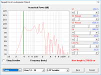
I did an MTH30 type sim'd fold for a TH using the LAB15, using the external dimensions of DAG's sub, and adjusted the mouth size until I got an Fb of 40 Hz. The resulting mouth is a bit smaller (another possible sign that the sim done for DAG's TH might be off - larger mouths = higher cutoff frequencies).
Anyway, here's the results. This doesn't strike me as a driver I'd use in a TH. Too much "ringing" around the ends of the passband. And this is with the "standard" model. Switch on the "Lossy Le" model and the response looks a lot worse. This is a driver that I'd try to use in a FLH or offset TL instead (depending on what I was aiming to accomplish).
Attachments
GM, yes those are the original links. His second drawing, filling in the numbers he first missed, isn't even to scale, and it all left me unable to decipher. But the design is very attractive to me given that it's smallish for what it claims to output. Although, measurements were never published, he says it went deeper than other drivers. There are obviously a few key differences to a lab type driver, mainly power compression from what I understand. But if it does 100 dB at 40hz, and plays a little lower in that form factor, I figure it's not bad.
I also have been talking to the Cubo designer, who claims a version of the Cubo can give 7dB gain and 33Hz cutoff with the Lab15, which almost seems too good to be true. But he also seems to know his math.
Honestly, for now, I'm looking at a low power system. I just want one or two subs that can actually put out outdoors, lower than people are used to hearing. They don't HAVE to slam super hard, but I'm also not wanting to just throw something together that will just fart and not sound good in an effort to go lower than it should.
Maybe there's a recommendation for a similar cost driver that will dig deep without too much power?
FWIW, the sim I did is bog simple, so should be easy to fold with Brian's software and goes a little lower, smaller with all that implies, yet only a ~3 dB less output [120+ dB transient peaks/m/2.pi/~35 -115 Hz in lossy Le mode], so either can do 100 dB from the low 20s to mid 120s with 80-100 W and just a few watts from 40 Hz.
GM
GM
- Status
- This old topic is closed. If you want to reopen this topic, contact a moderator using the "Report Post" button.
- Home
- Loudspeakers
- Subwoofers
- Dag's 40Hz TH