bjorno said:
I spent this weekend a lot of hours testing this Holliman phenomenon with a real setup (40L box and Peerless XLS 10”) and came to the conclusion that the high efficiency 5 to 25 Hz bandwidth probably is only a myth for this type of infra speaker.
In the design plans for the Holliman sub the 10 inch version calls for a resonant cavity with an internal volume of 100 litres. I'm not sure what was tested with the 40 litre box as stated above. It certainly wasn't a Holliman design.
Hey great work...
Do you think that folding a straight pipe up the side over the top and back down the other side would make any improvement (so loose the tapered sections that Holliman has on the top of the cabinet)? Also wondered if you wrapped such a pipe around the box cavity and loaded the driver over a port placed at one end of the box cavity. You could then try this driver/port position with one pipe end blocked off (closest to the driver), this would in the first case place the driver at about the 1/4 point of the pipe and with the blocked off end version at about 1/3 of the line. Past that I have no other ideas for this design but I am not at all surprised by your findings.
Lets hope that this will put an end to the painfully long drawn out mistery that is the Holliman Infra Bass that would appear in fact to have no base in reality. Best regards Moray James.
B, I believe you should have seen my last request by now, and with no reply I can only assume that you may not have followed the plans closely enough.
If any of the 3 circular holes is not aligned properly in relation to the others, and if the ports do not begin in between the driver and resonant chamber as detailed in the plans, this design has no chance whatsoever of working to spec. If it was built similar to the picture of the enclosure on one of the pages of graphs you attached then the graphs are right but it is not a Holliman box.
Freddi, I'm not sure what you are getting at. And who is Rob?
Holes....
Just a Guy, Just a question...
The indicated dimensions for the hole 'C' (The chamfered one) are they on 'smaller' side or the 'larger' side? (Top or bottom)
I'm building my 10" version! Made one out of scrap wood last week, with scrap woofer, scrap everything. Quite impressive, seen the horrible quality of the build! (Needed to fill old screw holes with silicone/caulking.. :-/ )
I'm not the one to express myself about the quality or other things, but it goes LOW... Much lower than anything else I build around this scrap woofer (Wicked One, Ripole, BR).
(And I got the wrong 'B' hole: 3" instead of 2"!)
good luck, more news to come during the build,
Paul
Mikey P:
Quote;
‘In the design plans for the Holliman sub the 10
inch version calls for a resonant cavity with an
internal volume of 100 litres. I'm not sure what
was tested with the 40 litre box as stated above. It
certainly wasn't a Holliman design.’
If you state it must be a 100L box for a 10” driver then a specific driver I don’t know the brand of and must be chosen for some for me unknown reasons.
Show me the data of the 10” rec. Holliman driver and a will tell you if there is any substance in your statement.
Of course my design is not a Holliman design it’s only my attempt to find out if the principle works like I do with many other designs I test for curiosity.
Show me a Holliman design with all information included as CSA’s and the specific driver in quest and I will consider building one and testing it in an acoustic laboratory I have access to.
moray james,
Please draw a picture, it would be very interesting to explore this more, and I have to admit that I have a problem to visualize the whole.
just a guy,
Quote;
‘But I would really
like to see a picture of your prototype model, in
particular, the part where the driver fires across
the beginning of the ports and into the resonant
chamber.’
Submitting a picture 1(2) I forgot to post, comparing the 20 L reflex box to a 20 L Holliman internal acoustic impedances and particle velocities i.e. the pressure load on the driver I really think reveals a lot of the so-called ‘unique loading method’, and 2(2) a drawing I i.e. made for my personal use only.
Quote;
‘B, I believe you should have seen my last request
by now, and with no reply I can only assume that
you may not have followed the plans closely
enough.
If any of the 3 circular holes is not aligned properly
in relation to the others, and if the ports do not
begin in between the driver and resonant chamber
as detailed in the plans, this design has no chance
whatsoever of working to spec. If it was built
similar to the picture of the enclosure on one of the
pages of graphs you attached then the graphs are
right but it is not a Holliman box.’
I have time now for the moment to respond and its up to me when I do.
Please show me a plan of approved Holliman, not those I can find here via DIY.com links where no secured performance data is submitted or shown with sloppy drawings but a drawing with all necessary data included preferably a box less than 100 L that will do fine in my home.
I really want to build one and to measure the performance.
Tell me why my box isn’t valid to verify the principle of Holliman.
I’ve spend some time reading and searching for documents that I hope beyond doubt give reliable information from someone who really have constructed a Holliman successfully, but found nothing.
I hoped to find documented measurements that would give me a fair chance to compare with, other than a lot of I think, un-quantified unsubstantiated hypothesises how this in principle should work, the patent papers included which claims that the efficiency is higher than for a Helmholtz type of speaker when actually the opposite is the true.
What performance should I expect to find (acoustic and electrical measurements) if I follow exactly a Holliman schematic that you have approved?
Without showing hard measurable facts as arguments to back up how a Holliman speaker performs I find it impossible for anyone to judge if my findings are wrong.
Unless there is something else hidden that I have missed or caused by my ignorance in this matter, I will immediately excuse and confess if I’m proven wrong.
With all physical data on my speakers I now have given, please inform me in a proper technical language, with facts I can understand, like any accepted electro-acoustical model that show in adequate quantifiable terms what is wrong with my test and prove that my attempt to show this principle is vague and wrong using those hard facts I’m asking for.
If you don’t and nobody else does, I will lean back on my own experiences from this and try my own way, hopefully to design a good infra-sub speaker, if possible, relying on my own knowledge.
By the way I’m on my second trial, a 55 L box with my 10” Peerless driver and have the plan to continue and finish this project within 18 days.
I have a sub bass project first to finish for a friend, a 340 L closed box with AURA NS18-992-4A that is to be used below 40 Hz.
Approved Holliman or not, in my new 55 L box will push the lowest resonance to about 11.5 Hz/81dB where the air velocity has is maximum and power handling is max 4 W RMS reaching the x-max at 2 Hz.
Now 11.5 Hz is the mean of a 2.32 octave bandwidth 5 to 25 Hz with Q =0.58 and also what I believe will be the box cut-off frequency (fb) using the same ports I have before.
The internal dimensions of the box is L=51.6 cm W=38.1 cm D=28.1 cm and a thickness off 37 mm.
Later I will also test a port system (slot-nozzle) I know can deal with high pressures and high air velocities and move the cut-off= fb down to towards fl that for my case will be about 8 Hz/78dB, the absolute lowest frequency I expect to reach when no closed room effects is added.
Slot nozzle port principles can be read here:
http://www.lam.jussieu.fr/src/Membres/Pellerin/pub/AES_112th_morkerken_parzy_pellerin_polack.pdf
http://www.lam.jussieu.fr/src/Membres/Pellerin/pub/pellerinAES116th.pdf
Thoughts:
Of course the ‘optimal air volume velocity to sound pressure transformer’ doesn’t exist’ for this any more than that you really could sense air puffs from the Holliman if you were close and as you also can from a ordinary reflex port.
Yesterday I read the document: ‘The Graham-Holliman Velocity-Coupled Infra-bass Speaker’
This statement intrigues me it sounds like sales arguments from a ‘White van:’
Quote:
‘This system is intended to compliment the normal ‘full range’ already being used in a Hi-Fi installation, to provide a musically satisfying and realistic sound, very close approximating live music set in its ORIGINAL acoustic environment rather than to measure accurately in terms of such parameters as harmonic distortion, delayed resonance, phase and transient response, when located in a controlled environment as an anechoic chamber.
This latter approach is likely to give very different results when a speaker is transferred to a domestic listening room.
However, if the system is measured, alongside the best of the (conventional) competition, IN THE CORRECT ACOUSTIC ENVIRONMENT, i.e. a domestic recommended size, it is likely that the difference will be just as it appears when listening tests are carried out in such and environment….’
Conclusions: The author doesn’t believe that this speaker should be put under a magnifying glass for unknown reasons where the test conditions are secured and the outputs are reliable and can be measured and compared scientifically?
Quote:
‘As I have stated elsewhere, these speakers succeeded, where other more conventional ‘Bass Bins fail’ because they are able to produce large amount of energy within the nominal range of 5Hz to 25Hz, at high relative efficiency and with VERY LOW audible distortion, and furthermore, they will do this in the small rooms commonly encountered in the domestic environment.’
Conventional speakers not only begin to cut off steeply below 30-50 Hz, even in the best available systems, but also, in general, their efficiency is order lower than the ‘infra-bass’ design in the range below 50 Hz, and furthermore their coloration and harmonic distortion are audibly much higher when used in the normal sized domestic lounge.
What is hidden behind this contradiction where quantifiable and measurable data suddenly appears?
How can this performance be claimed when no one can deliver any data?
B
2(2)
Quote;
‘In the design plans for the Holliman sub the 10
inch version calls for a resonant cavity with an
internal volume of 100 litres. I'm not sure what
was tested with the 40 litre box as stated above. It
certainly wasn't a Holliman design.’
If you state it must be a 100L box for a 10” driver then a specific driver I don’t know the brand of and must be chosen for some for me unknown reasons.
Show me the data of the 10” rec. Holliman driver and a will tell you if there is any substance in your statement.
Of course my design is not a Holliman design it’s only my attempt to find out if the principle works like I do with many other designs I test for curiosity.
Show me a Holliman design with all information included as CSA’s and the specific driver in quest and I will consider building one and testing it in an acoustic laboratory I have access to.
moray james,
Please draw a picture, it would be very interesting to explore this more, and I have to admit that I have a problem to visualize the whole.
just a guy,
Quote;
‘But I would really
like to see a picture of your prototype model, in
particular, the part where the driver fires across
the beginning of the ports and into the resonant
chamber.’
Submitting a picture 1(2) I forgot to post, comparing the 20 L reflex box to a 20 L Holliman internal acoustic impedances and particle velocities i.e. the pressure load on the driver I really think reveals a lot of the so-called ‘unique loading method’, and 2(2) a drawing I i.e. made for my personal use only.
Quote;
‘B, I believe you should have seen my last request
by now, and with no reply I can only assume that
you may not have followed the plans closely
enough.
If any of the 3 circular holes is not aligned properly
in relation to the others, and if the ports do not
begin in between the driver and resonant chamber
as detailed in the plans, this design has no chance
whatsoever of working to spec. If it was built
similar to the picture of the enclosure on one of the
pages of graphs you attached then the graphs are
right but it is not a Holliman box.’
I have time now for the moment to respond and its up to me when I do.
Please show me a plan of approved Holliman, not those I can find here via DIY.com links where no secured performance data is submitted or shown with sloppy drawings but a drawing with all necessary data included preferably a box less than 100 L that will do fine in my home.
I really want to build one and to measure the performance.
Tell me why my box isn’t valid to verify the principle of Holliman.
I’ve spend some time reading and searching for documents that I hope beyond doubt give reliable information from someone who really have constructed a Holliman successfully, but found nothing.
I hoped to find documented measurements that would give me a fair chance to compare with, other than a lot of I think, un-quantified unsubstantiated hypothesises how this in principle should work, the patent papers included which claims that the efficiency is higher than for a Helmholtz type of speaker when actually the opposite is the true.
What performance should I expect to find (acoustic and electrical measurements) if I follow exactly a Holliman schematic that you have approved?
Without showing hard measurable facts as arguments to back up how a Holliman speaker performs I find it impossible for anyone to judge if my findings are wrong.
Unless there is something else hidden that I have missed or caused by my ignorance in this matter, I will immediately excuse and confess if I’m proven wrong.
With all physical data on my speakers I now have given, please inform me in a proper technical language, with facts I can understand, like any accepted electro-acoustical model that show in adequate quantifiable terms what is wrong with my test and prove that my attempt to show this principle is vague and wrong using those hard facts I’m asking for.
If you don’t and nobody else does, I will lean back on my own experiences from this and try my own way, hopefully to design a good infra-sub speaker, if possible, relying on my own knowledge.
By the way I’m on my second trial, a 55 L box with my 10” Peerless driver and have the plan to continue and finish this project within 18 days.
I have a sub bass project first to finish for a friend, a 340 L closed box with AURA NS18-992-4A that is to be used below 40 Hz.
Approved Holliman or not, in my new 55 L box will push the lowest resonance to about 11.5 Hz/81dB where the air velocity has is maximum and power handling is max 4 W RMS reaching the x-max at 2 Hz.
Now 11.5 Hz is the mean of a 2.32 octave bandwidth 5 to 25 Hz with Q =0.58 and also what I believe will be the box cut-off frequency (fb) using the same ports I have before.
The internal dimensions of the box is L=51.6 cm W=38.1 cm D=28.1 cm and a thickness off 37 mm.
Later I will also test a port system (slot-nozzle) I know can deal with high pressures and high air velocities and move the cut-off= fb down to towards fl that for my case will be about 8 Hz/78dB, the absolute lowest frequency I expect to reach when no closed room effects is added.
Slot nozzle port principles can be read here:
http://www.lam.jussieu.fr/src/Membres/Pellerin/pub/AES_112th_morkerken_parzy_pellerin_polack.pdf
http://www.lam.jussieu.fr/src/Membres/Pellerin/pub/pellerinAES116th.pdf
Thoughts:
Of course the ‘optimal air volume velocity to sound pressure transformer’ doesn’t exist’ for this any more than that you really could sense air puffs from the Holliman if you were close and as you also can from a ordinary reflex port.
Yesterday I read the document: ‘The Graham-Holliman Velocity-Coupled Infra-bass Speaker’
This statement intrigues me it sounds like sales arguments from a ‘White van:’
Quote:
‘This system is intended to compliment the normal ‘full range’ already being used in a Hi-Fi installation, to provide a musically satisfying and realistic sound, very close approximating live music set in its ORIGINAL acoustic environment rather than to measure accurately in terms of such parameters as harmonic distortion, delayed resonance, phase and transient response, when located in a controlled environment as an anechoic chamber.
This latter approach is likely to give very different results when a speaker is transferred to a domestic listening room.
However, if the system is measured, alongside the best of the (conventional) competition, IN THE CORRECT ACOUSTIC ENVIRONMENT, i.e. a domestic recommended size, it is likely that the difference will be just as it appears when listening tests are carried out in such and environment….’
Conclusions: The author doesn’t believe that this speaker should be put under a magnifying glass for unknown reasons where the test conditions are secured and the outputs are reliable and can be measured and compared scientifically?
Quote:
‘As I have stated elsewhere, these speakers succeeded, where other more conventional ‘Bass Bins fail’ because they are able to produce large amount of energy within the nominal range of 5Hz to 25Hz, at high relative efficiency and with VERY LOW audible distortion, and furthermore, they will do this in the small rooms commonly encountered in the domestic environment.’
Conventional speakers not only begin to cut off steeply below 30-50 Hz, even in the best available systems, but also, in general, their efficiency is order lower than the ‘infra-bass’ design in the range below 50 Hz, and furthermore their coloration and harmonic distortion are audibly much higher when used in the normal sized domestic lounge.
What is hidden behind this contradiction where quantifiable and measurable data suddenly appears?
How can this performance be claimed when no one can deliver any data?
B
2(2)
Attachments
B, wow, that's a long post and I can't respond to it all, but here goes. First and foremost, I CANNOT BELIEVE that you did not use the plans because they were too "sloppy". When you make a "proof of concept" model you kind of HAVE TO follow the plans to prove or disprove the concept.
So let me say again - the picture you posted is NOT a Holliman box. The alignment and relative postioning of the holes is not correct. I believe your findings are all correct, the problem is that you were not testing a Holliman box.
I don't know how long you have been following this thread, or any of the provided links but I do not have the information you are requesting, that's why I brought this topic up again after it had been dead for two years. This is not a design that I "approved", it's just something I found on the internet.
If you have been reading my posts, you should know that I think the most important aspect of it is the "blowing across the mouth of a bottle" effect. This is acheived by the loading method, in particular, the alignment and the EXACT postitioning of the 3 holes and their relative distances from one another.
Bibster - I am under the impression that a larger hole C will mean a higher UPPER cutoff frequency, a smaller hole C will make for a lower UPPER cutoff frequency. This is just my theory on the whole thing and I could be wrong but I believe the tuning of the helmholtz resonator is responsible for the upper cutoff limit, the resonator WITH the extra length of output ports added determines the low frequency cutoff.
I would not worry too much about the extra inch in the size of your velocity coupling hole. Personally I will be trying small and making the hole bigger if necessary, but the purpose of the hole is to lower fs (according to the patent) and increase sensitivity. The box can be made with no velocity coupling considerations at all.
I would like some details of your build, please. In particular the driver used (specs I am interested in are qts, fs and vas) and the sensitivity of the design. I don't care if you measure with a meter or not, I just want to know if it keeps up with the mains. Also, how much power can it take before it hits xmax?
Maybe you can try a couple of different drivers with radically different qts? You could just hold the driver over the hole (without screwing it on) and test at low power just to get some impression of how different drivers will affect the outcome.
Hi bjorno,
You said in post #100:
""I spent this weekend a lot of hours testing this Holliman phenomenon with a real setup (40L box and Peerless XLS 10”) and came to the conclusion that the high efficiency 5 to 25 Hz bandwidth probably is only a myth for this type of infra speaker.::
I understood that to mean you were attempting to reproduce the Holliman 10 inch subwoofer design. My apologies if that is not what you meant. My statement that the design plans for the Holliman 10 inch version calls for a resonant cavity with an internal volume of 100 litres comes from the plans themselves. As to what spesific drivers the Holliman sub used, there was a reference made to the Richard Allan Atlas 15 woofer was used in the Holliman 15 inch version.. The T/S parameters of the Richard Allan Atlas 10, 12 and 15 inch drivers can be found here:
http://www.diyaudio.com:80/forums/attachment.php?s=&postid=384189&stamp=1083330126
I am still trying to verify if these were the drivers used in the Holliman design.
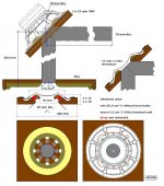
Sorry, but..... the way I read the .doc on the net, the resonant cavity is about 55 liters in the 10" version (Top: 78cm, bottom: 70.9cm, sides: 27.6 cm long and depth/width: 32cm)Mikey p said:
In the design plans for the Holliman sub the 10 inch version calls for a resonant cavity with an internal volume of 100 litres. I'm not sure what was tested with the 40 litre box as stated above. It certainly wasn't a Holliman design.
The build: (It's rebuild today!) made of 15mm MDF, thin top doubling: 3.2mm isorel/hardboard, battens: 20x30mm pine (30up).just a guy said:I would like some details of your build, please. In particular the driver used (specs I am interested in are qts, fs and vas) and the sensitivity of the design. I don't care if you measure with a meter or not, I just want to know if it keeps up with the mains. Also, how much power can it take before it hits xmax?
Maybe you can try a couple of different drivers with radically different qts? You could just hold the driver over the hole (without screwing it on) and test at low power just to get some impression of how different drivers will affect the outcome.
Hole 'B' (Coupling thinggy) is 50mm, Hole 'B' (the chamfered one) is 100mm (smaller side measured), chamfer is 45 deg. by jigsaw...
One of the sides is now glued to the rest, the other is screws only.
Couldn't cut, or have cut, the edged of panels 'F' (Sides of the cavity) under the right angle, so I just fit it, and caulked... (Yes, I should get a decent tablesaw....)
Didn't make pieces 'L' (Curved fillet) (yet?)
The pieces 'K' are yet to be fitted.... They don't seem needed to me... a 30Hz. wave wouldn't fit in the cavity ANYHOW... Please correct me if I'm wrong.
Now, the driver is the only 10" I have availible now... I said scrap, but should've said CRAP instead!! ah ah ah .... ahum.. anyhow: The T/S param's AS ADVERTISED by the constructor:
Qts: 0.45
Fs: 34
Vas: 145 (!!!!!)
Now, listening, very softly in my shop/garage, next to the childrens bedroom (11PM here)...
Crap!!!
Okay.... setup: iBook (iTunes), Edirol UA-25, Yamaha integrated amp --> G/H box
No tone control whatsoever.
Listening to Watermark (Enya) in mp3 (Has to be said!) and I can't hear any low, that is only mid. coming out of there...
Now, signalsuite please (os X tone gen.)... 30 sec. sweep form 0 to 100 Hz.
I can't give any graphs, so I'll just express myself...
")
Nothing, then ' WOW!!' then shortly back to 'nothing' then 'less impressive' the end
I guess the 'WOW' is 'round 25/30 hz... (Near Fs??)
Let's check...sinuses:
27 (naaah), 28 (hmm), 29 (getting there), 30 (almost), 31 (BANG!), 32 (BANG!), 33 less, 34 less etc..
REMEMBER THIS IS IN MY GARAGE, NOT A SUITABLE ENV.!!!!
Could be a room-mode or so.... (approx 10m long the garage...)
So far, not convinced... But neither was I with the scrap-build, sohoooo.... We'll see tomorrow! With my el-cheapo sub-amp @ 50Hz cut off (12dB I guess)
Anyhow, It doesn't keep up if I'll put it // to my mains (so far!) but hey, I've a really shitty driver in there!!
good luck, Paul
Thanks for the details. I think the problem is the driver. It should perform a bit better with all pieces screwed and glued, but for the most part I think the driver qts is too high. A lower q driver will exhibit more control during these resonances. Unfortunately lower q drivers are usually at least a bit more expensive.
I've tried putting the Atlas 15 specs into WinISD (if the Atlas is truely the driver this box was meant for) and it seems to be a high sensitivity pro-type driver meant for an incredibly small box. This type of driver's cone really doesn't want to move much and it's hard to get bass out of them without a horn.
I was worried about this from the beginning, because the driver I intended to use has a qts of .4. You can raise qts (and lower fs) by adding weight to the cone, but unfortunately I don't think there is anything you can do to lower q (without replacing parts of the driver).
I don't think there is any tweak you can do to the box to fix this issue (unless you want to add some type of chamber for back pressure on the other side of the driver, which is probably a bad idea). I think you need a lower q driver. But remember, I'm just guessing here, I'm no expert.
It MUST be the driver....
I'll see what I can get over here, for not too many pennies....
This driver I use(d) is some 10" 'pro'-driver, rigid accordeen surround, kaplan membrane. Cheap belgian brand or so (Sphynx audiosystems). As I said, I didn't spend a lot on it. At the time, I wanted to make a wicked one, and put 2 of those in there. YEs that's where the wood for the first scrap build came from
Any hint on easiely availible sub-drivers are welcome. The speakershop 'round here in Toulouse (Maison du hautparleur) carries some proper stuff?
I'm ready to spend no more than 100€ on it.
Please advise anyone (Something I could RE-use maybe?)
I'll keep you informed, Paul
Before spending a single penny on another driver which also may turn out to be unsuitable, I'd try a different approach. I may find myself in this situation soon, so I'll tell you what I'll do if it happens to me. To make absolutely sure you are getting the best performance out of the current driver, I would check on a couple of things first.
The first thing that comes to mind is the chamfer. I think the point of the chamfer is to make the length of the chamfered port essentially zero. If it is not chamfered enough, I think the port length is at least the thickness of the wood used; instead of zero, it's closer to an inch. That may not seem like a lot, but putting those numbers into a helmholtz resonator calculator shows that a difference in port length of fractions of an inch dramatically change the bandwidth and q of the resonator. Zero length port = wide bandwidth and low q, 1 inch port length = narrow bandwidth and high q. You mentioned that some of your work may be a bit rough, that's the only reason I bring this up, but I think the correct chamfer is essential to the operation of this box. I'd check my chamfer just to make sure it's as close to perfect as possible and if in doubt I'd chamfer it even more than 45 degrees.
Next I would be a bit worried about air leaks. You mentioned one side of your box is still loose. The best way to deal with that would be to screw and glue that side on of course, but if you don't want to do that I would line all of the touching edges with foam weatherstipping and then screw the side on. I don't trust an unsealed fit, a small air leak can ruin even the most perfect of designs.
After I had checked on these things and made absolutely sure that changing the driver is the only way to make things better, I would audition any driver I could get my hands on. It should be a quick and easy process, you don't even have to screw the driver in, just place it over the hole and run a low level sweep, then swap in the next driver. I would even make adapters to accept 8 and 12 inch drivers as well. I would want to try to audition as many drivers as possible before making a purchase. And not just different drivers, but drivers with considerably different parameters as well.
When looking for info on the Helmholtz Resonator I found this sitewww.phys.unsw.edu.au/~jw/Helmholtz.html , in the part about a guitar being a resonator they talk about a port without length and this seemed to fit what this sub design was going for. Your port length should be Radius X 1.7. The design I was working on came out to 37.5Hz to 6.78Hz with a .57499 cubic meter resonator and X1 length of 4.826 meters.
I don't think I will have any time to build it until summer, Holidays and 4 grand children birthdays, busy time of year for me.
I don't think I will have any time to build it until summer, Holidays and 4 grand children birthdays, busy time of year for me.
TwisterZ thanks for the great link. This is certainly very interesting information and surprised me a great deal. If I am understanding this correctly, a port with no length actually has a length of radius x 1.7. So if the hole is 6 inches and has no physical length, the port length is actually 5.1 inches. Am I missing something here or is that right? Anyway, this is the helmholtz resonator calculator I was using, it's the second calculator on the page. http://www.mhsoft.nl/Helmholtzabsorber.asp
If you have the time, I'd love to know what went into your calculations for the design you were working on. Just wondering how you came to your dimensions and how you know what the final tuning will be. Looks like your resonant chamber is considerably larger than the plans, the ports x1 are considerably longer and the frequency range is considerably larger than the original. So if you know exactly how to design for a particular frequency range, I'm really interested. I have some ideas about tuning but I'm nowhere near designing for performance as exact as you expect.
Also, I'd like your opinion on a suitable driver and maybe which driver you intend to use if you have picked one already.
Actually any information AT ALL would be greatly appreciated. I won't be able to build for at least a couple of weeks yet but I'd love to have enough information to design as precisely as you have.
JaG,
I've been paying a bit with the formulas offerd at that site: Pumped them into an Excel sheet.
Quite interesting results!!! Why didn't G.H. made the top of the resonator more like the vel. couping thing: Just a rather large (smoothed) hole, with a 'doubling' of thin material (==> no port length) over it.
I deduct that the 45deg. chamfer could be way 'smoother', in order to achive a null port length.
Have a look at my numbers (all in cm/m...)
Paul
Attachments
I'm not 100% sure that the purpose of the chamfer is to simulate zero port length, it's just my best guess.
Good work on the chart, there's a lot of work there and it illustrates how much small differences in port length affects output. Hopefully the calculator I linked to takes the "end correction" that is referred to in the link from TwisterZ is accounted for in the calculator parameters.
I had already considered using the same hardboard used for the velocity coupler for the "baffle" of the resonator as well but it all depends how much the hardboard costs. I may not use it at all.
This is the Resonator calculator I was using.
www.vk2zay.net/calculators/helmholtz.php
X=Radius X 1.7
X1=Length of second horn
Add these 2 together for the resonator calculator to get your low frequency cut off.
My notes are quite the mess so I will try to get this right.
The woofer will be infinant baffle on the rear, firing into a resonator 3.5" away from the restrictor plate that has a 6" hole (1/3rd the speaker). The port for the resonator is 9" with the back angled away inside the chamber. The X1 horn will start in the 3.5" gap on each side of the 9" port expanding out to the side then turning and expanding along side the resonator as it tappers to a point at the horn mouth.
- Home
- Loudspeakers
- Subwoofers
- Graham Holliman Velocity Coupled Infra Bass Speaker?