Nearly all of this forum is devoted to the problem of sequestering the rear wave of Rice-Kellogg drivers and without adding distortion to the front wave. Although it is inept engineering, almost all subs have resonances within their passbands.
The challenge arises since we are trying to move air using an inconceivably ill-matched heavier - but necessarily stiff - cone assembly, with ESLs and true horns excepted. And given the geometry, it is barely feasible to use an enclosure to separate rear waves from front waves without modifying the driver behaviour - with IBs excepted.
Using a long pipe to sequester the rear wave, such as my 17-foot thread has the following advantages.
1. If typically stuffed, no sensible resonance within the passband and good transient behaviour.
2. Sounds from the port are comparable to a fuzzy distance of about 24 feet and therefor do not peremptorily interact with the front wave except in a fuzzy way in a room.
3. Lowest frequencies coming from the exit port add to the FR and enable efficiency esp at low frequencies and exceptional low and sub-sonic bass.
A disadvantage, at least for my sub, is that it's about 13 cu feet, although it has only a 17 x 17 inch footprint. Also, more complex carpentry.
While folded 17-foot pipes are not for everybody, my point is that there hasn't been nearly enough creativity in addressing the rear wave problem. There are a familiar handful of enclosure archetypes that are seen in slight variation and driven by T/S models. For some reason people believe the silly "Iron Law". But more imagination would be nice.
B.
Last edited:
In what way is your loudspeaker (woofer slapped in a worse-than-rule-of-thumb 17-foot Transmission Line) different than a simple, non-optimal Transmission Line enclosure?While folded 17-foot pipes are not for everybody, my point is that there hasn't been nearly enough creativity in addressing the rear wave problem. There are a familiar handful of enclosure archetypes that are seen in slight variation and driven by T/S models. For some reason people believe the silly "Iron Law". But more imagination would be nice.
In what way your loudspeaker defies "the silly" Iron Law?
In considering a new sub, TLs with a long history of delighting audiophiles came immediately to my mind*. So I examined current thinking about TLs, although somewhat clouded, like tapped "horns", by a cult of devotees.
There's not much debate today about the nature of TLs or the main factors in their design (grandparental advice and some data not withstanding, stuffing is still mostly a superstitious exercise and is done "by ear" to taste... partly true of length as well). They behave like BRs except with a valuable additional set of variables available to the builder which has the potential to make the final speaker better or at least comparable to a damped BR ("aperiodic").
The typical modern QWTL (or variant, MLTL) has its basic tuning within the passband but also introduces a whole bunch of hideous upper noises too (although muffled). But if longer, like 17 feet and with a 8.5 Hz tuning, it would be wonderful.
BTW, giant irregular-shaped OBs work nice too.
B.
*like the phony named "tapped horn", TLs should also be in quotation marks... I guess "transmission line" (or even better "quarter wave.....") sounds much fancier than "pipe".
Last edited:
In keeping with my preaching about keeping flexible in post #1... it is true you have all kinds of options for the rear pipe (including stubs in various places, cross-section, bends, etc.). For example, it can be a true horn (growing in cross-section to the exit port) and it will give quality results accordingly.I keep considering Tapered lines for their low freq extension...
But when you add various artifices to the pipe - such as tapering (reverse of horn) and mass attacks - you push the pipe towards tuning and BR-like behaviour. Which seems quite the wrong trade-off to me.
B.
So, your 17-foot pipe is no different than mundane low-tuned MLTL, which can be simulated to 0.1 dB precision (or so) if you input TS parameters and box dimensions in the adequate software (for room influence, use CARA or similar). Conclusion: "the silly" Iron Law still rules.
By the way, I can't see the "8.5 Hz tuning" anywhere in your measurements.
Tuning in the passband above 16 Hz has its merit - to increase sound output above 16 Hz. "Hideous upper noises" are present in your measurements too - output at exit peaks at 250 Hz.The typical modern QWTL (or variant, MLTL) has its basic tuning within the passband but also introduces a whole bunch of hideous upper noises too (although muffled). But if longer, like 17 feet and with a 8.5 Hz tuning, it would be wonderful.
By the way, I can't see the "8.5 Hz tuning" anywhere in your measurements.
Every TL, including straight and yours, is tuned! Exit port in your TL has smaller area than the third pipe section, so you pushed it to a BR-like behavior (actually - MLTL).But when you add various artifices to the pipe - such as tapering (reverse of horn) and mass attacks - you push the pipe towards tuning and BR-like behaviour. Which seems quite the wrong trade-off to me.
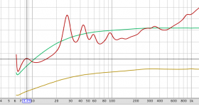
Your measurements clearly displays resonant behavior with peaks at 27-28 Hz and at 43-44 Hz, with light stuffing. Of course peaks are minimal with denser stuffing - just like regular TL.
I suspect what you are trying to convey is the goal of 'destroying the rear wave' without affecting the front wave of a speaker cone. If this is the case, and you meet that goal, you are losing quite a bit of sound output instead of using the rear wave in phase with the front wave in some manner via various enclosure designs.
Yes, exactly and to analyze it at the "level of discourse" that you've hit.I suspect what you are trying to convey is the goal of 'destroying the rear wave' without affecting the front wave of a speaker cone
There are just a handful methods of handing (or as I usually term it, "sequestering") the rear wave in common practice today for typical Rice-Kellogg drivers. The scarcity of alternatives is the first problem.
Generically:
1. as the correct engineering solution, you can use an impedance transformer (AKA true horn) with added advantages of directional control, or...
2. you can sequester the rear wave entirely with a sealed box (gaining degenerative feedback roughly comparable to an emitter follower) or an IB (which is also a correct engineering solution if you listen in two spaces),
3. you can return the rear wave to your room in a way that doesn't attenuate the wave excessively and doesn't interfere with the front wave excessively - at least in the passband of interest - with an OB or or labyrinth (including big detour with a 17-foot pipe),
4. using tuned enclosures, you can counter-act, inhibit, or even enhance some of the rear wave and return some part to the room with a BR, QWTL, or tapped "horn".
In post #1, I argued that a long pipe has nice advantages esp for going really low.
Jared's point about seeking to create a rear wave which is favourable in phase (which puts it in the tapped "horn" category) is hard to accomplish right at low frequencies and/or not just at one freq; a better approach is to view the returning wave statistically as distant, delayed, and/or randomly bouncing about the room as with a large OB.
B.
Last edited:
I do not think it is hard to accomplish with no constraints, but it is hard to accomplish with the added constraint of reasonable size / volume. I could easily do a 40 ft pipe in my home by utilizing dead space between floor joists for example. Other people might have attic space that is easily accessible, or might have space in the ceiling between the 1st and second floors. Others might find it easy to bury a concrete or plastic drainage pipe underground - there are all sorts of possibilities that are easy enough when you throw money at them and remove constraints around normal portable reasonably sized enclosures.
I am not sure what exactly it would get you though. 1/4 waves have been important because the wave has to travel in both directions, making it 1/2 wave total distance traveled.. What are you trying to do with 17 ft ? why not just call it an 18 hz TL?
I am not sure what exactly it would get you though. 1/4 waves have been important because the wave has to travel in both directions, making it 1/2 wave total distance traveled.. What are you trying to do with 17 ft ? why not just call it an 18 hz TL?
Right.I do not think it is hard to accomplish with no constraints, but it is hard to accomplish with the added constraint of reasonable size / volume...
At some long point, long pipes such as you imaginatively suggest for joists merge into IB and the rear wave doesn't add value except for being a non-boxy design.
At some short point, pipes become tuned quarter-wave tuned enclosures.
While I think clarity about concepts is important, no need for rigid adherence to any single concept in what you build... again, a kind of statistical argument (which some wannabee engineers are uncomfortable with). QWTLs when well-stuffed are hybrid designs.
"TL" (esp QWTL or MLTL) has become encrusted with true-believers; it is as inapt a name as "tapped horn". "Pipe" while not exactly chi-chi has no baggage, except for plumbing connotation.
BTW, don't you think it acts like an 8.5 Hz pipe?
B.
Last edited:
the wave length of 8.5hz is 133 ft?
Right. 133 divided by 8 is 16.6 feet. Closer than most of my real-world measurements.
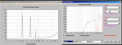
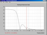
The plot below is the impedance of the ancient Stephens 150W in the unstuffed pipe. If you go from 8.5 Hz (roughly 133 divided by 16), you'll find bumps at the harmonics. The biggie at 27 Hz is the driver resonance.
The two smooth curves are the way I benchmark my impedance measurements; they are 7 and 10 Ohms. I'd say the impedance is pretty well behaved compared to a tapped-pipe or QWTL.
I might add, it is very hard to design with acoustic absorbents. So a big advantage of a really long pipe is that you can "sculpt" the low end since you have so much space for working with absorbents. Specifically, super-low notes can be passed through while blocking entirely the stuff over, say 35 Hz.
B.
Attachments
Last edited:
Are you trolling or just saying unusually peculiar things? Impedance plots tell you almost everything about cone motion.What is this impedence chart telling you about the acoustic output?
When I stick a speaker on the end of a 12.5 ft pipe, the impedance spikes do not align with the audio output like they do in a ported box...
Opposite to what you posted, a ported box is an example of cone movement not relating to audio output in the lower bass. That's why you can't apply motional feedback to a BR.
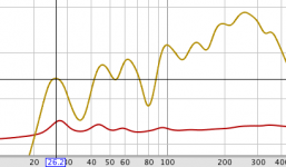
Attached is a plot showing impedance (as in earlier post) and audio output near the driver. Reasonable match, eh.
Depends on the "suspension" (or AKA the enclosure), but impedance (which is tied to back EMF) does reflect the VC motion and also roughly the sound output envelope, tuned enclosures excepted.
B.
Attachments
1/8 wave TL (pipe, whatever...)?! There is no such thing in the known universe.Right. 133 divided by 8 is 16.6 feet. Closer than most of my real-world measurements.
Are you trolling or just saying unusually peculiar things? Impedance plots tell you almost everything about cone motion
I must be saying peculiar things, trying to arrive at an answer. Not leading you to an answer, trying to arrive at an answer that I do not know.
I said audio output, not cone movement. I do not mean to be pedantic, but I know they are two different things. I think I chose my wording poorly though. My understanding of a ported box was that the tuning frequency of the port was the minima between the two impedance spikes. This might be incorrect, I learned this stuff 25 years ago in middle school from a 30 page radio shack book, and I do not claim to have a perfect memory. So the tuning frequency of the box / port is also the cone movement minima, where output is coming from port at a maximum.
I honestly never look at the impedance graphs as I had found them the least useful when building the simple types of boxes I have built in the past.
So back to the question around your impedance curve and the TL model I pasted above, what does the impedance curve tell you? The model I posted has spikes at 10hz, 32hz, 70hz and then smaller ones in the less interesting higher frequencies.
I have minimas for excursion at 18.5hz, 65hz which do not align with much in the impedance chart. I have audio output minima at 75hz, peak at 67hz, so there is a lot going on in the 65-75 hz range, but nothing that seems like an exact match. The 10 and 32 hz impedance spikes do not seem to tell me anything - maybe they tell me the tuning freqncy of the line? minima between them, just like ported box? 21 hz? I am attaching the other plots for this model as I thought a similar TL model to yours might tell me how to interpret yours, as like I said, I have always ignored the impedance curve, finding it the least useful.
Attachments
Glad to learn differences are partly just semantic. And glad you have an intellectual curiosity about long pipes.
Granted there are only a few elements like C, L, and R and their combination into tuned elements to work with in addressing the rear wave problem. I'm saying we should be more creative in how we use these in the messy world of speakers.
The listener's chair sound of a long, folded, well-stuffed pipe with an exit port about 24 feet from the driver is a complex mix-and-match of acoustic elements. As per my construction post, it seems to work pretty nicely in my music room.
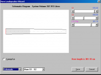
17 foot pipe sub 12-230 Hz ±5dB
The sound is output from the driver and from the exit port*, as is the case with a BR. As the plots in the construction thread clearly show, both the driver and the exit port sound are impacted (albeit quite differently) by the driver resonance (and cone motion is nicely reflected in the impedance plot), the total pipe length, wave effects within each of the three segments of the folded pipe (the segments were intentionally made different in cross-section shape and the doors between irregular**), and damping (which is different in each segment).
Better than a BR, a long pipe (and other TLs) is a design with better "levers" for you to control damping ("aperiodic") and very low bass. Also more flexible as furniture - my 7 foot tall box takes just 17 x 17 inches on the floor.
B.
*and in my case with ¼-inch plywood, from the walls too
**good to design irregularity to foster a more stochastic result
Granted there are only a few elements like C, L, and R and their combination into tuned elements to work with in addressing the rear wave problem. I'm saying we should be more creative in how we use these in the messy world of speakers.
The listener's chair sound of a long, folded, well-stuffed pipe with an exit port about 24 feet from the driver is a complex mix-and-match of acoustic elements. As per my construction post, it seems to work pretty nicely in my music room.
17 foot pipe sub 12-230 Hz ±5dB
The sound is output from the driver and from the exit port*, as is the case with a BR. As the plots in the construction thread clearly show, both the driver and the exit port sound are impacted (albeit quite differently) by the driver resonance (and cone motion is nicely reflected in the impedance plot), the total pipe length, wave effects within each of the three segments of the folded pipe (the segments were intentionally made different in cross-section shape and the doors between irregular**), and damping (which is different in each segment).
Better than a BR, a long pipe (and other TLs) is a design with better "levers" for you to control damping ("aperiodic") and very low bass. Also more flexible as furniture - my 7 foot tall box takes just 17 x 17 inches on the floor.
B.
*and in my case with ¼-inch plywood, from the walls too
**good to design irregularity to foster a more stochastic result
Last edited:
Just re-discovered another very long pipe speaker. which outwardly closely resembles mine.* This speaker is mix of long pipe and Karlson-15 with possibly some pseudo-horn (TH) in there too.** But wth lots of stuffing unlike other K-15s. Again, superior clean bass at 20 Hz and below.
See post #9:
http://www.diyaudio.com/forums/full-range/320847-karlson-cabinet.html#post5510402
B.
*
17 foot pipe sub 12-230 Hz ±5dB
** Has anybody commented on the similarity between a Karlson box and a pseudo-horn? Not saying there is any direct link and the origins of the "tapped horn" are murky. But they really do seem similar to me the way the Karlson rear wave curls around to connect with the front wave inside the box, like a TH.
Last edited:
- Home
- Loudspeakers
- Subwoofers
- Long pipe to sequester rear wave