I realise there is another ongoing thread which discusses aspects of this paper BUT, i would like this thread to concentrate on the ICT's.
Interesting such theory & Actual implimentation described & shown in this PDF.
Amongst everything else of interest in there, in particular see,
Interesting such theory & Actual implimentation described & shown in this PDF.
Sensorless Velocity Feedback Subwoofer by Robert-H Munnig Schmidt http://rmsacoustics.nl/papers/whitepaperMFBdesign.pdf
Amongst everything else of interest in there, in particular see,
3 Further Improvements on Modelling
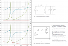
Figure 12: LT-spice model of the full system where the semi-inductance is modelled as a series of four inductances with three parallel resistors. A compensation network is added to cancel the remaining e?ect of the semi-inductance. Based on initial model of J.M.Plantefève.
@ TBTL
Ahh, sorry ! Here's the correct link http://rmsacoustics.nl/papers/whitepapervelocityfeedback.pdf
@ P.Lacombe
Hi, can you provide any links etc to your work ?
Ahh, sorry ! Here's the correct link http://rmsacoustics.nl/papers/whitepapervelocityfeedback.pdf
@ P.Lacombe
Hi, can you provide any links etc to your work ?
I'm sure some of you will have been following the Lossy le progress in the Horn Response thread, & why it can make a BIG difference between sims and real builds. So that's why this is important !
*
They use drivers designed & built by Atohm.
*
The motor: FWI TM Technology (Force Without Inductance)
Coil interaction interferences have been taken into account in such a way that the inductance value remains very low and constant whatever its position. To obtain this, a specific geometry was designed for the core and for the copper ring which fits onto it.
Technology | Waterfall Audio
They use drivers designed & built by Atohm.
Thank you.@ TBTL Ahh, sorry ! Here's the correct link http://rmsacoustics.nl/papers/whitepapervelocityfeedback.pdf
I've read this series of PDF's but did not spend too much time on velocity feedback. If I understand it correctly, it is the opposite of current drive: it decreases the output impedance (makes it even negative to partially cancel Re) in order to obtain more electrical damping, while current drive increases output impedance in order to skip impedance (so also inductance) to make a direct link between 'amplifier drive' and 'electric effect of the coil'.
Sorry I haven't. Le is important if you drive your woofers using a voltage source, as most amplifiers do. But it appears that sensorless velocity feedback (on it's own) does not help too much, as stated on p. 20-21 of your PDF. If it does not work, why would you pursue this approach?I'm sure some of you will have been following the Lossy le progress in the Horn Response thread, & why it can make a BIG difference between sims and real builds. So that's why this is important !
Adding feedback shows no reduction of the second harmonic distortion and only a 3 dB reduction of the third harmonic distortion
which does not support the statement that the increased damping will result in less excitation by harmonics around the fundamental frequency (42 Hz)
Later on in this series of PDF's, the author settles at current drive + motional feedback using an acceleration sensor mounted on the voice coil. Klippel has got a poster on which it describes Le as function of both current and position: https://www.klippel.de/fileadmin/_migrated/content_uploads/Klippel_Nonlinearity_Poster.pdfUnfortunately the beneficial effects are only observed sub-resonant as can be seen from Table 1 for the same output level as with the example at 20Hz from Figure 15. It seems even that above 60 Hz the distortion rises slightly, mainly in higher harmonics. Considering the limited accuracy of the measurements and the fact that these numbers are already quite moderate and measured at a very high sound power level, the application of positive current feedback appears to give only a very limited reduction of the distortion.
Le is not relevant anymore when you use current drive, as the Lorentz force the coil exerts on the cone is directly related to current (and magnetic field strength), not to voltage. When using current drive, electrical damping is lost, so it requires motional feedback using a sensor, which is not practical. So I understand why you would like to solve the problem of Le in a different way.
")
Last edited:
[I can't edit my previous post anymore, so I am posting this here:]
I hope I understand this discussion correctly. There are two aspects: (1) frequency response of built cabinet does not match Hornresp simulation, (2) reduction of harmonic distortion.
If there is a difference in frequency response between sim and practice, then either the Hornresp model is incorrect or the cabinet is not built to match the assumptions done in the Hornresp simulation. If electric countermeasures are to be taken, I would simply pre-EQ the signal going to the amplifiers using a fixed EQ instead of basing it on current feedback.
Those PDF's are written with another point in mind: reduction of harmonic distortion. The author puts all frequency response shaping in a pre-filter. My previous post is about distortion reduction.
Last edited:
@ Zero D,
What exactly is it that you are interested in?
- how best to model woofer semi-inductance(aka lossy inductance) so that modeling program results will better match reality?
or
- how best to compensate for the existing semi-inductance so passive crossovers and/or feedback loops will behave better?
or
- how best to design woofers so the semi-inductance effects are minimized?
Inductance cause an instability in feedback loop, so it is mandatory to cancel it. I have discovered this many years ago (... 1975 ?)
I thought a Zobel network fixed that ?
The capacitor in the Zobel will soak up any back EMF.
They do the same with power factor correction. Add capacitance to damp the motors inductance.
I thought a Zobel network fixed that ?
The capacitor in the Zobel will soak up any back EMF.
They do the same with power factor correction. Add capacitance to damp the motors inductance.
Yep, that works from the amplifier's point of view.
However, modern subwoofer drivers often have extremely high inductance, which means their frequency response below 100Hz does not follow what would be expected from a simple T/S simulation. Hornresp gets much closer with the Lossy Le function.
Some way of dropping the inductance of these modern subs to make them easier to work with would be rather nice - switching on Lossy Le invariably makes the frequency response quite a lot worse.
Chris
The Lossy Le function does tend to move things in the right direction for the type of woofers used to develop the correction factors. Basically BL is adjusted downward in an attempt to account for increasing inductance at lower frequencies coming from the semi-inductance due to “skin-effect” in the iron core. Again it does tend to move things in the right direction, but it is trying to account for a frequency dependent effect by changing a frequency independent parameter..modern subwoofer drivers often have extremely high inductance, which means their frequency response below 100Hz does not follow what would be expected from a simple T/S simulation. Hornresp gets much closer with the Lossy Le function.
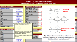
The best way to improve modeling of woofer response is to ditch the simple T/S model and adopt a more “advanced” model, like the semi-inductance model mentioned by Zero D. Scanspeak has begun supplying parameters for this model on the last page of their data sheets. (attached is an example) Both REW and ARTA already calculate the 3 additional parameters needed for this model. The semi-inductance is a little pesky to implement in a modeling program, but not too bad. DMcBean does have the literature on this model, so hopefully at some point it will find its way into Hornresp as an option.
More details on the model can be found in these Thorborg papers. (attached in case the links break)
http://www.bnam2012.com/papers/Thorborg_31.pdf
http://www.bnam2012.com/papers/Thorborg_32.pdf
Yeah, putting long solenoids of wire around big hunks of iron in search of longer stroke has the unfortunate side effect of high inductance. One way to minimize inductance is to use short-coil long gap geometry (Aura). Another way is to use the so-called differential drive configuration which has two voice coils in separate gaps which are wound in opposite directions. This arrangement will have less effective inductance than the equivalent single voice coil, since the mutual inductance between the counter-wound coils will subtract rather than add to the inductance of the individual coils. (JBL, Rockford, Velodyne, etc) I’d wager that these methods aren’t more common because they increase cost over the traditional single long coil motor configuration. In comparison, EQ to fix the response is cheap…well, provided the existing amplifier is up to the task.…Some way of dropping the inductance of these modern subs to make them easier to work with would be rather nice
Attachments
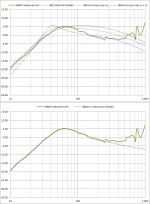
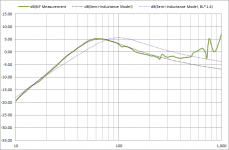
As an example comparison of the semi-inductance model with the traditional and Lossy-Le models, here is a Dayton Classic 12” woofer in a 64Ltr sealed box I measured/modeled late last year. The traditional model shows the expected response for Qtc~0.7. Of course this looks nothing like the measurement which exhibits the undesirable “inductance hump”. You can see that the Lossy-Le adjustment used by Hornresp does move things in the right direction, but the curve shape is not converging on the measured response. Just for grins, I added a blue curve with double the recommended Lossy-Le adjustment to see the trend of how the shape was changing with BL reduction.
I think the response from the semi-inductance model speaks for itself. Not perfect, but quite an impressive improvement in match with the measurement. The fact that the model has matched measurement for a wide variety of woofer types is a good indication that the dominant electro-magnetic effects of semi-inductance, shorting rings, air-gap width, and under/over-hung voice coils are being captured properly. In my opinion, well worth the cost of having to keep track of 3 additional parameters.
The second pic shows a comparison of the measured free-air impedance vs. the two models. The red curve at the bottom of the plots is the inductance of the blocked impedance model. Notice that for the semi-inductance model the inductance is 1.6mH at 1kHz(same as for the traditional model). But, it is 5mH and rising as frequency gets below 100Hz. This is due to the skin effect in the iron core. A simple way to think about it is that as you go down in frequency the magnetic field from the VC penetrates further into the iron core. So, the inductance increases as more and more iron is effectively added inside the VC.
Attachments

The Lossy Le function does tend to move things in the right direction for the type of woofers used to develop the correction factors. Basically BL is adjusted downward in an attempt to account for increasing inductance at lower frequencies coming from the semi-inductance due to “skin-effect” in the iron core. Again it does tend to move things in the right direction, but it is trying to account for a frequency dependent effect by changing a frequency independent parameter.
The Lossy Le formula was created for some very specific reasons.
1. The only simulation program I know of that will accept these extra inductance parameters is Unibox which is incapable of simulating about 90 percent of the enclosures I'm interested in. It can only do ported and sealed.
2. I asked Mr McBean about adding capability to accept the 3 inductance parameters needed to do this type of inductance correction. He said absolutely not IIRC.
3. It's not easy to get these 3 necessary parameters. The VAST majority of manufacturers don't provide them. Sure, REW and ARTA will measure them but that's only going to help if have the drivers on hand. Most of the drivers that are badly affected by this inductance issue are pretty expensive so buying them all just to get t/s is not feasible.
4. Even the earliest and simplest version of the Lossy Le formula produced results that were remarkably more accurate than a simple sim and in some cases the sim and measurements are almost perfect overlays (disregarding a sensitivity difference).
The Lossy Le tool was never expected to be perfect but it's a large step in the right direction IMO.
The best way to improve modeling of woofer response is to ditch the simple T/S model and adopt a more “advanced” model, like the semi-inductance model mentioned by Zero D. Scanspeak has begun supplying parameters for this model on the last page of their data sheets. (attached is an example) Both REW and ARTA already calculate the 3 additional parameters needed for this model. The semi-inductance is a little pesky to implement in a modeling program, but not too bad. DMcBean does have the literature on this model, so hopefully at some point it will find its way into Hornresp as an option.
More details on the model can be found in these Thorborg papers. (attached in case the links break)
http://www.bnam2012.com/papers/Thorborg_31.pdf
http://www.bnam2012.com/papers/Thorborg_32.pdf
Your sim shows a great correlation with the measurement, thanks for showing it. Perhaps I should recommend that people use this model if they have Unibox and can obtain the necessary parameters and only need to sim sealed or ported boxes.
Yeah, putting long solenoids of wire around big hunks of iron in search of longer stroke has the unfortunate side effect of high inductance. One way to minimize inductance is to use short-coil long gap geometry (Aura). Another way is to use the so-called differential drive configuration which has two voice coils in separate gaps which are wound in opposite directions. This arrangement will have less effective inductance than the equivalent single voice coil, since the mutual inductance between the counter-wound coils will subtract rather than add to the inductance of the individual coils. (JBL, Rockford, Velodyne, etc) I’d wager that these methods aren’t more common because they increase cost over the traditional single long coil motor configuration. In comparison, EQ to fix the response is cheap…well, provided the existing amplifier is up to the task.
In response to the bolded part, I think the reason is at least twofold.
1. The big manufacturers are not making long stroke drivers. Since the drivers they are making are not incredibly susceptible to this issue there's not much reason to innovate.
2. The smaller companies that are making long stroke drivers don't understand the issue and I'd bet most wouldn't believe you if you did tell them about it. That's the reaction I got from Stereo Integrity. Even after being presented evidence he doesn't believe the issue exists or that the Lossy Le tool can more accurately simulate it.
I don't think the issue is cost. It would conceivably cost a lot less to design and manufacture a dual coil dual gap speaker than to make the motor 10, 20, 30, maybe even 40 percent larger to overcome the lossy inductance losses.
Howdy3. It's not easy to get these 3 necessary parameters. The VAST majority of manufacturers don't provide them. Sure, REW and ARTA will measure them but that's only going to help if have the drivers on hand.
Good to see you back on diyAudio.The comment concerning REW and ARTA was supposed to be aimed at the manufactures, not the end user. Both software packages are currently used by many manufacturers, so it would be easy for them to start including the extended inductance model parameters. Back in the 80s it was tough to get even the basic TSP from most manufacturers, but slowly that changed. With one manufacturer already including the semi-inductance parameters in their datasheets…hopefully more will follow.
Understood, and that is how I described it “…moves things in the right direction…”.… The Lossy Le formula was created for some very specific reasons…was never expected to be perfect but it's a large step in the right direction IMO.
I won’t quibble over the size of the step.
Unibox does contain an additional [R||L] term, but unfortunately does not include the semi-inductance parameter needed to properly model the LF behavior. BTW, Unibox also models 4th order bandpass enclosures, although now that I think about it the port “transmission line” model is in error similar to WinISD.…Perhaps I should recommend that people use this model if they have Unibox and can obtain the necessary parameters and only need to sim sealed or ported boxes.
Discrepancy between WinISD & HornResponse (#12, #15)
You could be right, I’m certainly not an expert in woofer design or manufacture.I don't think the issue is cost.
My thought was that having to retool and/or order unstocked specialty parts would have a monetary impact, especially on the smaller manufacturers.
In case you weren't aware, simply increasing BL will not overcome the effect of the semi-inductance on the response. The shape of the response is mainly coming from the electrical filter effect of the inductance on current thru the voice coil, not from the motor being severely underdamped. Bumping up magnet strength by 40% in an attempt to compensate for what looks like an underdamped woofer will not have the desired effect. If the blocked impedance remains the same the response shape will stay roughly the same, but appearing to shift to the right. Basically you will gain output above resonance by the expected amount(~3dB), but lose output below resonance because of overdamping. (see attached example)…make the motor 10, 20, 30, maybe even 40 percent larger to overcome the lossy inductance losses.
Attachments
Scanspeak has begun supplying parameters for this model on the last page of their data sheets. (attached is an example) Both REW and ARTA already calculate the 3 additional parameters needed for this model.
Hi bolserst,
Can you help me please, I am a bit confused at the moment
.It would seem that the Scanspeak data sheets specify five additional parameters for the semi-inductance model, not three:
Resistance [Re']
Free inductance [Leb]
Bound inductance [Le]
Semi-inductance [Ke]
Shunt resistance [Rss]
(The values of resistance [Re'] and bound inductance [Le] are different to those specified elsewhere in the sheets for DC resistance [Re] and voice coil inductance [Le]).
Am I missing something here?
Also, it would have seemed more logical for bound inductance be designated as [Leb] rather than [Le], and free inductance to be designated as [Le] rather than [Leb]
.Kind regards,
David
- Status
- This old topic is closed. If you want to reopen this topic, contact a moderator using the "Report Post" button.
- Home
- Loudspeakers
- Subwoofers
- Inductance Cancellation Techniques