Hello,
Someone known, simulated or measured the Forward Aspected Ratios for different subwoofer designs?
What is the FAR for TH design?
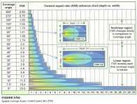
Note about far: Conceptualized coverage shape as rectangle with proportional length and width. The rectangle insludes only the frontal lobe of the response, hence the name "forward aspect ratio (FAR)" The FAR shape connects on-axis far (length to off-axis near (width). The aspect ratio rises as speakers coverage angle narrows.
coverage / FAR
The street term for this is "throw".
Someone known, simulated or measured the Forward Aspected Ratios for different subwoofer designs?
What is the FAR for TH design?
Note about far: Conceptualized coverage shape as rectangle with proportional length and width. The rectangle insludes only the frontal lobe of the response, hence the name "forward aspect ratio (FAR)" The FAR shape connects on-axis far (length to off-axis near (width). The aspect ratio rises as speakers coverage angle narrows.
coverage / FAR
360º / 0,5
180º / 1
90º / 1,41
60º / 2
30º / 3,9
etc
The street term for this is "throw".
If by "Forward Aspect Ratio" (FAR) you mean Directivity Index (DI), given the assumptions of the Hornresp program, it is unlikely that it could simulate the DI of a "TH" over it's usable bandwidth, given the differences between cabinet frontal area and "horn" exit areas, interior corner and folding arrangements, and depth differences between the two virtual sources of front and back radiation which seem to exhibit some degree of "cardioid" behavior from a single driver.
If by "Forward Aspect Ratio" (FAR) you mean Directivity Index (DI)
The FAR definition I found on the book: Sound Systems: Design and Optimization: Modern Techniques and Tools for Sound System Design and Alignment Autor Bob McCarthy
The author indications this definition for loundspeakers.
https://www.amazon.com/dp/0415731011/ref=pe_2740240_232593710_TE_dp_1
The directivity Index (DI), I saw only used for Horns applyed with compressions drivers
Hi-fi ( = small size and large wavelengths) monopole subwoofers are nearly omnidirectional, independent on whether they are ported, tapped horn etc.
Thanks but while the concept is clear, I've been looking for numbers
Your link to 606's book still does not give any indication of FAR being anything but a different name for DI or Q factor, with a correspondingly different numerical value, different "numbers" for the same information.
A bass FLH (front loaded horn) is a compression driver applied to a horn.
At low frequencies a typical portable FLH in free space has a Q of 1, a DI of 0dB, a FAR of .5, in it's upper range it could vary from a Q of 3 or more, a DI of 5 or more, a FAR of 1.41 or more.
In small rooms the DI at low frequency makes no difference, in large rooms arrays can be used to influence DI of LF if desired.
For a bass horn to be large enough to effect a large change in Q, DI, or FAR at low frequencies it would require mouth dimensions as large as the frequency of control, not going to happen with a single portable FLH.
A TH, having two virtual sources within one horn, does appear to have more forward directivity (higher Q, DI, or FAR) numbers than a FLH of similar size.
Dave Gunness of Fulcrum Acoustic has purpose designed single driver passive cardioid bass reflex cabinets with far higher forward directivity than TH designs.
Bass arrays are often used in "cardiod" or "end fire" formation, using combinations of multiple drivers and time delay to reduce rear radiation, which in turn can increase Q, DI, or FAR more than possible in a single driver design.
Cheer,
Art
You are right, I've checked other sources and they are the same thing at the end.
There are some math in the document below that I may use to ask David if it's possible to implement in hornresp at least "partial directivity".
https://www.princeton.edu/3D3A/Publications/Tylka_3D3A_DICalculation.pdf
Thanks a lot for the numbers.
The multiple cab arrengement to active cancel rear radiation is very interesting but probably more applicable to big events.
There are some math in the document below that I may use to ask David if it's possible to implement in hornresp
at least "partial directivity".https://www.princeton.edu/3D3A/Publications/Tylka_3D3A_DICalculation.pdf
Thanks a lot for the numbers.
The multiple cab arrengement to active cancel rear radiation is very interesting but probably more applicable to big events.
Pro Audio Software, A/E Specifications, Manuals, EASE, Data Sheets, Brochures, White Papers, Flyers, & more Downloads by Electro‑Voice
Check out the white paper by EV. Haven't read it myself in a while, but may be useful to you
Check out the white paper by EV. Haven't read it myself in a while, but may be useful to you
You will likely find David has already put as much directivity simulation into Hornresp as will work.There are some math in the document below that I may use to ask David if it's possible to implement in hornresp
The multiple cab arrengement to active cancel rear radiation is very interesting but probably more applicable to big events.
Arrays for directivity are more applicable to large venues, but Fulcrum Acoustics one box, one speaker, one amp approach CS series brings real cardioid behavior (near -10 dB at 180 degrees over most of the sub range) into a typical box size also applicable for smaller events.
Attachments
Could you indicate the tool? i didn't find it. Would be nice if he can plot some colored chart.
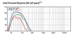
To be more direct and also to make the subject more easy to understand, I decided to digitalize two images from the book, they are such a small part that I don't think copyright would be a problem.
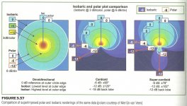
First the author make some assumptions using isobaric and polar plot - Attachment #1
Then regarding the ratio from width and depth he defines FAR - Attachment #2
To be more direct and also to make the subject more easy to understand, I decided to digitalize two images from the book, they are such a small part that I don't think copyright would be a problem.
First the author make some assumptions using isobaric and polar plot - Attachment #1
Then regarding the ratio from width and depth he defines FAR - Attachment #2
Attachments
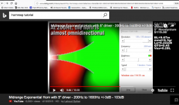
I have not personally used the tool, and don't recall it's name, but you should find it in the Hornresp instructions.Could you indicate the tool? i didn't find it. Would be nice if he can plot some colored chart.
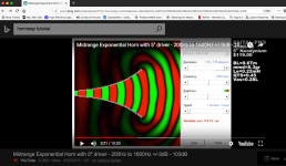
It produces nice colored charts that graphically illustrate dispersion at different frequencies, as you can see from these two shots from an on-line tutorial.
Attachments
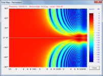
Would be nice if he can plot some colored chart.
Something like the attached, perhaps?
.Attachments
- Status
- This old topic is closed. If you want to reopen this topic, contact a moderator using the "Report Post" button.
- Home
- Loudspeakers
- Subwoofers
- Subwoofer Forward Aspect Ratio (FAR)