Hey Mark,
Photobucket has eaten all the measurements I've posted, but I'll upload them somewhere else when I next get a chance.
Upload them here, and they won't be subject to the whims of another Internet site/provider..
")
Upload them here, and they won't be subject to the whims of another Internet site/provider..
How to do it? all time I click on the insert image button it allows me just to insert just an external link.
How to do it? all time I click on the insert image button it allows me just to insert just an external link.
Under "Additional Options", select "Manage Attachments".
The rest should be self-explanatory.
Yes, but found a really good deal on an active Behringer 18. $350 shipped. Just did a gig with it and was half decent with 6db boost at 40hz (sound familiar?). QSC would probably take it… I had a good chuckle. My oldest DJ’d and we got it setup and she was kind freaking it was too loud (in a gym) and told me I was gonna get her in trouble. Sure enough, advisor comes over… Asking her if we could turn it……………… UP!Hey Sam,
Weren't you thinking of building one of these at one point?
Would love to have someone else that's tried them to back up my raving about how good they are.
... Or to tell me I'm crazy.
Cheers,
Chris
Interesting times we’re living in. I have a few other hobbies such as homebrewing and I make beer better than ALOT of pros so I am not surprised at all that a DIY sub builder could do the same. There is some serious knowledge here in addition to having killer tools like HR and REW etc.
Under "Additional Options", select "Manage Attachments".
Thanks
make beer better than ALOT of pros so I am not surprised at all that a DIY sub builder could do the same.
We can extend this sentence to almost everythink, people sometimes don't know about the power they have, or sometime they are simple lazy. Consentrate resources at big companies is not good from social point of view. Many small companies (even one person) are much better then a big one.
This is the good thing about new softwares generation at smartphones. Small companies now can have a worldwide visibility through internet.
Sory to extend off topic
Hey Mark,
Photobucket has eaten all the measurements I've posted, but I'll upload them somewhere else when I next get a chance. Likely a couple of days time.
The long-and-short was the response slopes down from 100Hz to 40Hz by around 4dB. A filter with a Q-factor of 1 at 40Hz levels this pretty much perfectly.
There's also a rise above 100Hz up to 160Hz, where the response starts getting choppy (higher frequencies making it out of the port).
The simulations came out quite close to the measurements IIRC, and I find them very useful when you take their limitations into account.
Cheers,
Chris
Thanks Chris, I'd be particularly interested in any calibrated spl measurements, that show efficiency.
I'm on a major sub hunt / rethink.
The mid boxes I built that you simmed for me are working out better than hoped.
I just measured their efficiency vs a PM90 ......mid section against mid section, 100Hz to 650Hz passband, and response flattened for each of them through that passband
My box is within 0.2dB !!!! I was expecting to take a hit against the PM90's horn loading.
Lordy I'm gonna need some major new sub power.
Trying to learn as much as I can about sub alternatives now...
(....sorry for the swerve...)
Cheers, Mark
Under "Additional Options", select "Manage Attachments".
The rest should be self-explanatory.
The file sizes are really limited for attachments here. Quite understandable, but rather annoying when I have to re-size everything.
I've sorted out hosting for now (hidden away in my website), so it's just a case of putting things back where they were.
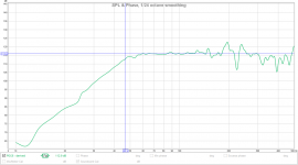
However, here's the comparison with the Hornresp sim:

Pretty close if you ask me. Actual tuning has come out at 38Hz, rather than the 41Hz predicted in the Hornresp sim, and the pipe resonances are pushed up a little higher.
It's important to remember that Hornresp doesn't consider the folding of the port, so the angles there change things a little.
I tried the Lossy Le function, and found the response diverged much further from what I've measured. The PA drivers in use here aren't really what that function is aimed at - it's more for high-excursion home/auto drivers with voicecoils that are 2" diameter and 2" long.
Mark,
I haven't done any calibrated SPL measurements since, at the time, I didn't have a multi-meter I trusted.
Given how close the Hornresp sim is to my measurements in shape, IMO it'll probably be right about the sensitivity, too, which comes in around 95dB@2.83v at the bottom end, and 98dB at 100Hz on the sim. You can compare the simulation to the measured response above (taken at a few feet IIRC) and figure out the sensitivity from there. I think saying it's around 96dB@2.83v as a broad-band number would be sensible.
It's difficult to compare the sensitivities of two different cabinets when EQ is in play. If one had all boosts and the other all cuts and they end up at the same level, who's won? Better, IMO, to compare without any EQ at all, just highpass filters for driver protection.
Chris
Actual tuning has come out at 38Hz, rather than the 41Hz predicted in the Hornresp sim, and the pipe resonances are pushed up a little higher. It's important to remember that Hornresp doesn't consider the folding of the port, so the angles there change things a little.
Was that the Fb measured by looking for the minimum driver excursion by measuring SPL via a close mike? I remember you ending up with some strange results via that approach. It's not a method I'd recommend at all, for reasons mentioned previously. Measuring the impedance/phase is the best approach. Still the sim vs. actual response suggests that Fb is a little lower than sim'd. Hornresp pretty much nails it if the path length around the folds is measured via the advanced centerline approach (my POC6 build for example came in exactly as predicted). Do you have an image of your build's layout? I'd like to have a closer look.
I like how the vent resonances are pushed above 200 Hz, giving a nice wide passband. How high do you actually use them?
I tried the Lossy Le function, and found the response diverged much further from what I've measured. The PA drivers in use here aren't really what that function is aimed at - it's more for high-excursion home/auto drivers with voicecoils that are 2" diameter and 2" long.
Yup. However I've seen it being suggested for other builds, but I haven't seen any *actual* builds where the build's response as measured by the DIYer was a closer match for the sim when lossy Le was enabled. Hence my curiosity.
Attachments
Mark,
I haven't done any calibrated SPL measurements since, at the time, I didn't have a multi-meter I trusted.
Given how close the Hornresp sim is to my measurements in shape, IMO it'll probably be right about the sensitivity, too, which comes in around 95dB@2.83v at the bottom end, and 98dB at 100Hz on the sim. You can compare the simulation to the measured response above (taken at a few feet IIRC) and figure out the sensitivity from there. I think saying it's around 96dB@2.83v as a broad-band number would be sensible.
It's difficult to compare the sensitivities of two different cabinets when EQ is in play. If one had all boosts and the other all cuts and they end up at the same level, who's won? Better, IMO, to compare without any EQ at all, just highpass filters for driver protection.
Chris
Thanks Chris, looks good !
FWIW, I've come to the conclusion the only sensitivity spec i care about anymore is with all crossover filters in place, and response EQed flat within the passband.
So for comparing subs' efficiency, I want to see both HPF and LPF in play, as I intend to use them.
Also, what good is a response peak within that bandwidth if I know I need to knock it down ?....Doesn't leaving the peak in to measure efficiency just give a false inflation?
By the same token, if there is a dip in response that I know I want to raise with EQ, don't I want to see how much that lowers efficiency ?
If I put HP,LP, and EQ in place, I can directly compare different boxes.
I like to send pink noise to the boxes, and average SPL and voltage for a minute or two.
Then it's just a little math to make very valid, real usage comparisons I think....
I mean, this reflects real word IMHO. (if the design goal within the passband is flat response)
Let's me determine how many boxes and how much power, will I really need when it's all said and done.......
Guys, am I missing something here...this method seems pretty simple and intuitive....
.....makes me wonder why it hasn't been being used for a long time.....
Cheers,
Mark
Last edited:
Which is which?
For a non-eq'ed, smallish cab, that red one is pretty impressive.
Red is the simulation, green is measured.
As I said above, the simulation is pretty close, especially when you consider that it's only doing the maths on straight pipes, and this is folded.
Was that the Fb measured by looking for the minimum driver excursion by measuring SPL via a close mike? I remember you ending up with some strange results via that approach. It's not a method I'd recommend at all, for reasons mentioned previously. Measuring the impedance/phase is the best approach. Still the sim vs. actual response suggests that Fb is a little lower than sim'd. Hornresp pretty much nails it if the path length around the folds is measured via the advanced centerline approach (my POC6 build for example came in exactly as predicted). Do you have an image of your build's layout? I'd like to have a closer look.
I like how the vent resonances are pushed above 200 Hz, giving a nice wide passband. How high do you actually use them?
Yup. However I've seen it being suggested for other builds, but I haven't seen any *actual* builds where the build's response as measured by the DIYer was a closer match for the sim when lossy Le was enabled. Hence my curiosity.
From the top...
- Impedance/phase said it was around 37Hz IIRC, driver minimum excursion was more like 39Hz. It's a difference of a couple of %, which is fine IMO. Nobody will ever notice a 1Hz tuning difference - air temperature will have effects of that sort of order. When I moved the mic around on the cone (<0.5" away), I could get a null anywhere from 39Hz down to 25Hz so I quickly ditched that method.
- The final build is here: http://www.diyaudio.com/forums/subwoofers/272492-teeny-tiny-pa-15-subwoofer-12.html#post4939160
I went for the one with 3 port panels and a 48L chamber volume.
- I usually run up to around 120Hz, where they hand off to some 2x10" tops. 4th order crossovers all-round.
- IIRC, my 2x JBL GTO1214 in a sealed cube were closer with "Lossy Le" enabled. They're the right sort of drivers for that feature. If you like, I'd be happy to split a new thread and discuss that further as I think further discussing that here would dilute this thread, which I was hoping would stay fairly compact.
Thanks Chris, looks good !
FWIW, I've come to the conclusion the only sensitivity spec i care about anymore is with all crossover filters in place, and response EQed flat within the passband.
Cheers,
Mark
I understand why you think it's the best way to do it, but consider this:
Two speakers. One has a big horn bolted to the front that gives it a 10dB sensitivity advantage from 400Hz-2kHz. Otherwise both are perfectly flat. If you apply some EQ to the one with the horn, both will be perfectly flat. Now, compare them.
If you measure them now, you'd say they're both flat and neither has an advantage, unless you can monitor the exact power inputs for both cabinets required to produce a given SPL. Measuring the exact power input is really difficult to do - a simply voltage reading won't do it, as that doesn't incorporate the speaker impedance. You'll also need a very very good meter that can spot that a couple of octaves has less power than the other, in the mash of pink noise.
It's better, IMO, to use a fixed-voltage sweep and see which one's louder where.
The measurements are much more straightforward, and give you information about where in the frequency range each cabinet is at its most sensitive - a 12" midbass that happens to need very little power at 5kHz isn't a whole lot of use, but one that does that at 80Hz is much more useful.
Chris
Thanks for reposting Chris but already I considered this design a success. Time to move on to the Teeny Tiny 18 with 30hz f3.
Well, there is a nice-looking 18" Void driver (1400N) in the second-hand shop near me. Basically zero information online about it, so I don't think it'll sell for a while.
Might go and make a cheeky offer...
Though I've no idea what I'd do with it. Tiny18, maybe, but the 15"s are so good. I'd want a lot of the 18"s before I could replace the 15"s.
Actually, it'd be pretty cool for a HT setup - those JBLs have a lot of distortion, so I wouldn't mind moving those on.
Hmmmm....
Chris
If you measure them now, you'd say they're both flat and neither has an advantage, unless you can monitor the exact power inputs for both cabinets required to produce a given SPL. Measuring the exact power input is really difficult to do - a simply voltage reading won't do it, as that doesn't incorporate the speaker impedance. You'll also need a very very good meter that can spot that a couple of octaves has less power than the other, in the mash of pink noise.
Chris
Hi Chris, it's really easy to measure exact power.
Today's voltmeters do averaging at very low cost; even true RMS is getting cheap.
I find it easy to get average voltage readings I trust to 2 decimal places.
Same thing with current.
Take averages, SPL and voltage, and you can at least quote efficiency referenced to voltage, which seems to slowly be becoming the norm.
If you want to take it a step further, take average current over the same period, to find a measured "nominal" impedance for the passband.
And yes, if you try to span a different number of octaves, ie use different HP and LF filters, you cannot directly compare.
But the point in my mind is....why would I ever want to do that?
Hi Chris, it's really easy to measure exact power.
<snip>
And yes, if you try to span a different number of octaves, ie use different HP and LF filters, you cannot directly compare.
But the point in my mind is....why would I ever want to do that?
I more meant that a multi-meter might struggle to resolve a bit of EQ happening over a bandwidth of an octave on a signal covering many octaves.
Didn't realise they were getting as good as you suggest.
Chris
- Impedance/phase said it was around 37Hz IIRC, driver minimum excursion was more like 39Hz. It's a difference of a couple of %, which is fine IMO. Nobody will ever notice a 1Hz tuning difference - air temperature will have effects of that sort of order. When I moved the mic around on the cone (<0.5" away), I could get a null anywhere from 39Hz down to 25Hz so I quickly ditched that method.
- The final build is here: http://www.diyaudio.com/forums/subwoofers/272492-teeny-tiny-pa-15-subwoofer-12.html#post4939160
I went for the one with 3 port panels and a 48L chamber volume.
I ran the sim in Hornresp and it suggests a lower resonance frequency of 42.4Hz. A measured resonance frequency of 37 Hz is a difference of 12.7% is actually pretty high, and the equivalent of adding 20cm to the length of the vent. If we consider 39 Hz at the lowest resonance frequency, it's still about 8% off of what the sim suggests.
Assuming you're not using any stuffing in the vent, I'd guess that the difference is due to the sim not accurately describing the mouth of the vent (it's close though, so I suspect any difference it make will be minor) and that with the vent's entrance being basically on the side of the box and near to the top panel, it's getting loaded so the effective length is quite a bit longer. I ran into exactly the same type of issue with my INF10 build, where I had to significantly reduce the vent lengths (compared to the sim) to achieve the target Fb because they were being loaded by the box so much. Looking at the layout of your box, I'd be tempted to use a jig saw and start removing slices of the first panel to see if I could move the Fb closer to the target. That's of course if I wanted to aim for a bit more efficiency in the passband. If it's a non-issue, I'd leave it as it is and enjoy the lower Fb, LOL.
It does highlight though a hypothesis that I've held for awhile - the "advanced centerline" approach for mapping out a path is only really accurate when there are no large discontinuities in the path that's being mapped (in this case the discontinuity is where the internal box volume meets the start of the vent). When you have these discontinuities, its accuracy drops.
In any case, I think you found a really good way of shoe-horning a 15" driver into a box that small and getting below 40 Hz out of it. It's height and width are basically set by the driver and the vent - there's almost no leeway at all to play with. it's actually smaller than my POC6 which is slightly more sensitive, and that build only gets down to 48 Hz, with a 12" driver...!
Yup. However I've seen it being suggested for other builds, but I haven't seen any *actual* builds where the build's response as measured by the DIYer was a closer match for the sim when lossy Le was enabled. Hence my curiosity.
As Chris mentioned, this isn't the type of driver that the Lossy Le feature is for. Although Josh Ricci mentioned he uses the Lossy Le setting for ALL drivers, I designed it specifically for the long stroke drivers that exhibit noticeable deviant behavior compared to how they sim.
In that context, I haven't seen a single build (diy or otherwise) that didn't match a Lossy Le sim better than a simple sim. There's 30 examples in the development study alone, one of which was a diy'er build, the rest were built by Ricci (not sure if he's a diy'er or an industry pro now). All the designs and measurements are open source and free so anyone can replicate the results I've shown.
There have been a few since then too but I haven't kept track. I haven't seen a single one where a driver of this type wasn't best described by the Lossy Le sim.
It's not a perfect prediction by any means, and Ricci mentioned it tended to overshoot a bit (he said he simulates both ways, with and without, and the build usually comes out somewhere in the middle closer to the Lossy Le end). But it does seem to work very well when applied to the right type of driver.
Last edited:
Would like to build 4 of these subs small enough for my small suv. I have 1 HP1060 new in a box and will get 3 more. I will build these for DJ setup. I have a smallish amp Crest 7001 have not used since factory refurbished 2018 in storage. I'll probably get a 3600VZ to power the 4 subs. But was thinking also Chris about a top hat while on its side to accommodate a BFM SLA Pro's built 8 years ago as per plans but used Faital 6FE200 instead. I've used it with Tuba 24's loaded with 2 BP102's not enough bass. The SLA are bright maybe because of the piezos. I just bought a Berry 15 per side EQ, will be using these with the system. Chris any plans on making any tops for these subs, would like to see your double 10" tops, and also your finished product of the Tiny subs. Thanks
Last edited:
Hi,
Some thoughts:
1 - You're going to need a bigger amplifier. Aim for 1KW per driver, minimum. 2KW would be better for peaks. The Crest 7001 would leave a lot of performance on the table. I used a Crown MA12000i for a while, and then moved to a Powersoft T602.
2 - I don't think much to the BFM designs. The priorities don't really hold up in this day and age.
3 - Yep, you can stick a top hat in these subs. No problem there.
4 - The plans for the 2x10" tops were done on the back of an envelope, long since lost. They're not a special design in any way - just some really good drivers in a sensible ported box.
Chris
Chris I know the power requirement, as I am small DJ company with 4 different sound systems for different requirements. I was also looking at the CVR amps from China very powerful and there's a CVR 1004 has 4 channels at 1000 watts each for $899.00. I have heard these amps are being bought there in UK and here in the US.
Also Chris which plans in this site Teeny Tiny PA 15 use the HP 1060? You have 2 plans side by side the first one has an added panel in the port top altogether 4 panels, then you have the second plans without that extra panel in the path with only 3 panels. Which one should I build for the 15HP1060? Do you have pics of the finished cabs? Thanks
Also Chris which plans in this site Teeny Tiny PA 15 use the HP 1060? You have 2 plans side by side the first one has an added panel in the port top altogether 4 panels, then you have the second plans without that extra panel in the path with only 3 panels. Which one should I build for the 15HP1060? Do you have pics of the finished cabs? Thanks
- Home
- Loudspeakers
- Subwoofers
- Chris's "Teeny tiny PA 15" sub (Horn) - Final Version?