Thinking to build a TL with added path-length modules, kind of like a natural horn with "crooks" (AKA "shanks") added for tuning. If the first iteration doesn't work right in my room, I'll just slip in (or remove) a module to re-tune the path length*.
Ever seen it done?
Thanks.
B.
*I used to slip bricks into the rear sealed chamber of my Klipshorn bass for tuning. Maybe it was just the weight that helped the sound.
Ever seen it done?
Thanks.
B.
*I used to slip bricks into the rear sealed chamber of my Klipshorn bass for tuning. Maybe it was just the weight that helped the sound.
Please see post #8 for my antic summary of TL theory, as I understand it this morning.
Transmission Line with passive radiator
B.
Transmission Line with passive radiator
B.
Thinking to build a TL with added path-length modules, kind of like a natural horn with "crooks" (AKA "shanks") added for tuning.
*I used to slip bricks into the rear sealed chamber of my Klipshorn bass for tuning. Maybe it was just the weight that helped the sound.
I believe that crooks in prison use shanks, occasionally fashioning them from toothbrushes, etc...
The bricks thing makes me think you are a perfect mark for this sort of scam:
Totem Acoustic Beak | Stereophile.com
I believe that crooks in prison use shanks, occasionally fashioning them from toothbrushes, etc...
The bricks thing makes me think you are a perfect mark for this sort of scam:
Totem Acoustic Beak | Stereophile.com
In your rush to ridicule, you seem to be ignorant of the following:
1. you don't know musicians sometimes call natural horn "crooks" (added lengths of tubing) "shanks",
2. you are clueless about the physics of how the rear chamber of a horn speaker with a sealed rear chamber works and
3. against forum rules, your post lacked any useful contribution to the thread.
B.
you seem to be ignorant
I am not, but I'm sure it makes you feel better to assume so. So you want to tune your transmission line to play in different keys?
") Or perhaps your mistrust of simulators has you interested in a modular cut and try approach?
Or perhaps your mistrust of simulators has you interested in a modular cut and try approach?No, because TL software simulations are accurate.Ever seen it done?
Ummm, you might have overlooked this heated discussion at Parts Express. Post #12 shows 3 dramatically different variations in measured performance arising from adding handfuls of wool.No, because TL software simulations are accurate.
ML transmission line vs. Bass reflex - Techtalk Speaker Building, Audio, Video Discussion Forum
The otherwise several well-informed participants in this long thread (all post "MJK" modelling, I'd guess) can't make up their collective mind whether we are talking about a 4th order or 2nd order or maybe mostly one of the other except at low frequencies.
Great and very civil discussion. I think it leads me to believe that the mushier is the concept, the more adherents turn to "true belief" rather than evidence.
No question the physical world can be modelled and simulated to some degree. But, in contrast to Sonce's authoritative pronouncement, I wonder if the elements here are too fluid, irregular, or hard to parameterize too precisely today?
B.
Last edited:
Ummm, you might have overlooked this heated discussion at Parts Express. Post #12 shows 3 dramatically different variations in measured performance arising from adding handfuls of wool.
I believe those are simulated results, not measured results. Quoting from the same message: "To illustrate, I did some modeling for an RS225-8 in a "true" TL. I made the line's length 127" so that its 1/4-wavelength resonant frequency of 26 Hz was appropriate for the driver's 26-Hz Fs and Qts of 0.4..."
Basically he simulated the results of adding various amounts of stuffing to the TL.
Thank you for correcting me. Sad, I was hoping it was data. Maybe Sonce will post the data that shows sims and reality are alike as he says.Basically he simulated the results of adding various amounts of stuffing to the TL.
The Parts Express charts simulate changes as handfuls of wool are added. This results in large variations. Indeed, there are changes in the very character of the speaker; I can think of nothing analogous with BR boxes unless you left the back cover loose.
In so far as the sim predicts results, it shows you are still mostly just guessing as you throw handfuls of fluff into your TL. Yet the results can be quite dramatic.
What is it we are arguing about?
Can we please get back to ideas for add-on piping.... just in case the sim isn't perfect.
B.
Last edited:
No, you overlooked that post #12 shows simulations directly from Martin J. King software.Ummm, you might have overlooked this heated discussion at Parts Express. Post #12 shows 3 dramatically different variations in measured performance arising from adding handfuls of wool.
The otherwise several well-informed participants in this long thread (all post "MJK" modelling, I'd guess) can't make up their collective mind whether we are talking about a 4th order or 2nd order or maybe mostly one of the other except at low frequencies.
A TL is naturally a 4th order design (ie it has a hole in it), but if damped till aperiodic can be 2nd order and i have seen actual measurements that seem to show an aperiodic box with 1st order roll-off — possibly justthe initial roll-off.
Because of the chameleon nature an arguement between roll-off order in meaningless.
dave
The Parts Express charts simulate changes as handfuls of wool are added. This results in large variations. Indeed, there are changes in the very character of the speaker; I can think of nothing analogous with BR boxes unless you left the back cover loose.
The output of BRs will vary quite a bit when stuffing is added too. Any direct alignment that relies on some sort of resonance to augment the output of the driver will be impacted by stuffing, as stuffing will affect the resonance "Q" of the alignment.
In so far as the sim predicts results, it shows you are still mostly just guessing as you throw handfuls of fluff into your TL. Yet the results can be quite dramatic.
The sims remove a lot of the guesswork as to how and where to apply the stuffing. My recent "Boom Unit" build is a subwoofer that I modelled as a MLTL (though it looks just like a slot-loaded sub with an extra internal panel). The sims suggested that I could drop Fb a few Hz with some stuffing in the S1 area, and my measurements bore this out. The response slopes off a little faster than that predicted by the sim, but I put that down to two things (1) Hornresp does not include the impact of box losses on the response, and (2) the test signal was HP's at slightly below Fb.
I plan to do a similar build based on the PA310 driver when my Xmas vacation starts, but the process will be the same - sim with stuffing, build, stuff as sim'd until Fb matches. I will do more measurements with that build, e.g. impedance curve, to see how close the Hornresp sim gets to reality. I suspect that the peaks will likely be lower (that losses thing), but the resonance frequency should be very similar, if not the same.
In summary, you can trust the Hornresp sims, once you understand what impact box losses might have on the results.
the results of adding various amounts of stuffing to the TL
A TL requires the terminus to have a low pass function or there will be significant ripple in the passband due to the unwanted line harmonics. Adding more and more stuffing decreases the ripple and if sufficient is added the primamry harmonic starts to be affected as well, add enuff and the line becomes aperiodic with near nothing coming out the terminus (a good thing in a midTL or when trying to heavily damp a high Q driver (like the Visaton B200).
MJK (and too a lessor extent Augspurger) introduced some over tricks to aid in the low pass function allowing for less damping and more fundemental (ie greater bass support from the back of the driver). Mass-loading, offset driver, the real nature of what a narrowing taper do (pushing the harmonics up and allowing for less damping), th erole of bends in a folded line (of particular interest in BLH).
The nature and characteristics of various damping material as far as the sims go is still not well defined and we see lots of “stuff to taste” comments in TL designs.
dave
Or maybe you can show one and only one simulation form M. J. King or Augspurger software which don't correspond to reality? Burden of proof is yours.Maybe Sonce will post the data that shows sims and reality are alike as he says.
Wrong! Simulations shows pretty accurate how much handfuls of fluff to throw in TL to obtain the simulated (and measured!) frequency response.In so far as the sim predicts results, it shows you are still mostly just guessing as you throw handfuls of fluff into your TL. Yet the results can be quite dramatic.
That is going back to the Stone Age of loudspeaker designing: cut-and-try.Can we please get back to ideas for add-on piping.
MJK (and too a lessor extent Augspurger) introduced some over tricks to aid in the low pass function allowing for less damping and more fundemental (ie greater bass support from the back of the driver). Mass-loading, offset driver, the real nature of what a narrowing taper do (pushing the harmonics up and allowing for less damping), th erole of bends in a folded line (of particular interest in BLH).
Offsetting the driver makes a significant difference, as you can basically eliminate the effect of lowest peak caused by the resonances, as can be seen from the sim below. That's the sim'd output from my Boom Unit's vent - grey is with the driver offset, and red is with it mounted closer to the start of the line. I cringe when I see new TL designs these days that don't take advantage of this simple tweak to extend the passband of the design.
Attachments
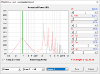
Yes as Brian demonstrates, there are more interesting variations you can fool-with in a TL than in a BR. Which, allowing the additional carpentry, should appeal to us in the DIY crowd. More generically, a BR is just a big single-note tuned coke-bottle*.Offsetting the driver makes a significant difference, as you can basically eliminate the effect of lowest peak caused by the resonances... I cringe when I see new TL designs these days that don't take advantage of this simple tweak to extend the passband of the design.
But this thread (and the other one too) show (1) the "cult" element among adherents and (2) the squishiness and debatable quality of the theory, at least to folks who aren't cult members.
B.
*Does that sound like something you want in your music system? To make a long story short, the solution is the use drivers with sub-sonic resonance.
Last edited:
To make a long story short, the solution is the use drivers with sub-sonic resonance.
So both of your threads are one big troll then? Move over cult of transmission line, enter the cult of the infinitely baffled
acoustic suspension advocate. Damn, that AR-1 bass must be so tasty.Until such time as choices of sub-sonic resonance drivers are available*, we need to address the rear wave problem with Rice-Kellogg drivers.
As I have been absolutely explicit about, I believe TL approach makes more sense than BR, allowing for the added complexity and other challenges.
I regret that this thread has gathered some snarky and inappropriate comments like yours. But nobody has yet posted a single creative suggestion for making a TL box with a means of adjusting the path length.
Ping.
B.
*it's not smart to design music reproduction systems with resonances... and worse yet if you then have to go to a lot of trouble combatting the resonances
Last edited:
...or if it's an MLTL, you can have the vent exit the rear of the box, where you can add a removable shelf vent that runs up the back of the box. Then just size that removable shelf vent to taste. Just bear in mind that in doing so, the optimum position for the offset driver will shift as well.
Having an adjustable TL (rather than an MLTL) might be a bit more difficult, as adjusting the path length also requires adjusting the taper, which means making an adjustment along the entire length of the TL.
IMO, I wouldn't do it. Sims are accurate enough to predict the response of a TL. Just make sure you sim the response that you really want to achieve or fix the response with EQ.
Having an adjustable TL (rather than an MLTL) might be a bit more difficult, as adjusting the path length also requires adjusting the taper, which means making an adjustment along the entire length of the TL.
IMO, I wouldn't do it. Sims are accurate enough to predict the response of a TL. Just make sure you sim the response that you really want to achieve or fix the response with EQ
.- Status
- This old topic is closed. If you want to reopen this topic, contact a moderator using the "Report Post" button.
- Home
- Loudspeakers
- Subwoofers
- Transmission Line with "crooks"