I'm looking to build a subwoofer from sonotubes and sewerpipes. I'd like a flat-ish response from 30-100Hz min. I only need 110db max, and its for music.
The BP6 has flat response and covers the range I need without getting too big or requiring transforms to fix it. The BP8 has 5db ripple that I could never eliminate. I realize a box may be easier, but I want a cylinder to match other speakers.
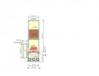
Below is a drawing of what I intend to build as well as the HornResp design. I have added a 4th order BW low pass filter at 160Hz. The structure is as big & tall as I'm willing to go.
The BP6 has flat response and covers the range I need without getting too big or requiring transforms to fix it. The BP8 has 5db ripple that I could never eliminate. I realize a box may be easier, but I want a cylinder to match other speakers.
Below is a drawing of what I intend to build as well as the HornResp design. I have added a 4th order BW low pass filter at 160Hz. The structure is as big & tall as I'm willing to go.
Attachments
First question.
I have a -3db point around 28Hz but would like 25Hz. Can anyone comment on the effect of adding fiberglass fill (or other fill) to chamber #1 to make this chamber "appear" larger so I can get a lower -3db point ???
That's a very interesting project you're planning there!
Fiberglass fill in a vented cabinet will reduce the resonance frequency and the "Q" of the vent output. Lining is ok, but stuffing might likely result in a reduction in output. I suggest just trying to detune it a bit by increasing the length of the vent connecting the two sections. For in room response, you might actually get better results with a passband response that gently slopes down to -3dB @ 30 Hz, rather than as flat as possible down to the lowest resonance frequency.
With your particular design, as the connecting vent is actually external, you could plan the build to allow you to swap in different lengths to get the best results.
From the diagram, it looks like you're planning to have three vents from one cabinet. This can make fine tuning a pain in the butt. I suggest using one large vent instead, like the 6" precision port available from Parts Express, and face it downward. That will leave only one vent to trim, and you can fin-tune the response by varying the distance from the end of the vent to the floor (i.e. raising the cabinet).
I'm looking forward to seeing pictures of the build!
Brian, thanks for the advice on the fill.
All the tuning ports will be accessible to allow tuning if required. It would be easy to lengthen the external pipe P1, after the build, and slope more gradually into the 20's at the expense of some flatness and droop in the 30's.
If the bottom vents P2 are made from the same 10cm sewer pipe (78cm2). I would need multiple pipes around the bottom perimeter (maybe 5 pipes). I might rethink this. I could use a single larger pipe as you suggest. I could also do this by making the bottom port from a space between 2 discs and tune via disc spacing.
Max power and displacement
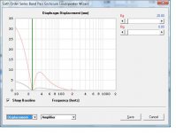
Does anyone use mechanical stops to prevent exceeding Xmax?
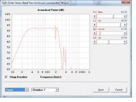
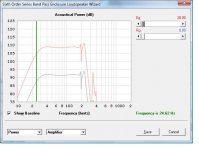
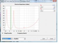
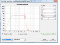
I've provided a few more graphs that indicate the max pressure I can get is about 108db at 20rms (=20rms^2 /4=100W) at the Xmax of 9mm. I think this is at the standard 1m, but I'm not entirely sure what HornResp uses.
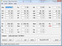
I'll be using a Dayton DCS305-4 (12"), Sure aa-ab31282 (200W class D) and a Qualtek QPDF-320-36 (36VDC supply, 320W). Parts should arrive over the next week.
In reality this amp can deliver ((36vdc-1vdc)pk * 0.703rms)^2 / 4 = 153W to a 4 Ohm load. The power supply has spare capacity for my future bi amp'd speakers est (2*75W + 2*30W + 100W = 310W). The amp also seems to have a high pass somewhere <20Hz, but they're not clear on it. I need to attenuate f<20Hz anyways as the x-displacement would be too large and not audible.
Does anyone use mechanical stops to prevent exceeding Xmax?
I've provided a few more graphs that indicate the max pressure I can get is about 108db at 20rms (=20rms^2 /4=100W) at the Xmax of 9mm. I think this is at the standard 1m, but I'm not entirely sure what HornResp uses.
I'll be using a Dayton DCS305-4 (12"), Sure aa-ab31282 (200W class D) and a Qualtek QPDF-320-36 (36VDC supply, 320W). Parts should arrive over the next week.
In reality this amp can deliver ((36vdc-1vdc)pk * 0.703rms)^2 / 4 = 153W to a 4 Ohm load. The power supply has spare capacity for my future bi amp'd speakers est (2*75W + 2*30W + 100W = 310W). The amp also seems to have a high pass somewhere <20Hz, but they're not clear on it. I need to attenuate f<20Hz anyways as the x-displacement would be too large and not audible.
Attachments
Last edited:
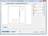
Something's weird here. That impedance response suggests only one resonance frequency in the 20's. However, given a Vb of 12 litres and a port with area of 506 cm^2 will be extremely high resonance frequenccy, over 150 Hz. If that's the case, it may be better to not have a front volume at all. And given a rear volume of 62 litres with a vent of 4" diameter that's 43.5" long will result in a resonance frequency of 18 Hz or below.
I suggest validating the sim in another program that can simulate series-tuned bandpass enclosures before committing to a build.
I suggest validating the sim in another program that can simulate series-tuned bandpass enclosures before committing to a build.
I suggest validating the sim in another program that can simulate series-tuned bandpass enclosures before committing to a build.
Or perhaps use a more recent version of Hornresp, noting that relatively small changes to chamber and port tube dimensions can significantly alter the positions of the resonance frequencies.
How? I would expect any stop to do more harm than goodDoes anyone use mechanical stops to prevent exceeding Xmax?
How? I would expect any stop to do more harm than good
There would be a limit stop disc mounted in front of the woofer, with a small overlap with the rubber suspension ring. It would prevent the cone from extending too far and damaging the voice coil. The limit disc could even have a soft foam surface to cushion the impact and (hopefully) not crush the cone edge on impact.
Or perhaps use a more recent version of Hornresp, noting that relatively small changes to chamber and port tube dimensions can significantly alter the positions of the resonance frequencies.
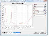
Fair enough. I loaded the most recent 42.40.
There is a difference at around 200Hz as the peak increased, so I lowered my LP filter from 160Hz to 150Hz, reduced chamber #2 from 10L to 7L, and decreased the port2 area from 500cm2 to 360cm2 to compensate. New graphs and design file posted.
Something's weird here. That impedance response suggests only one resonance frequency in the 20's. However, given a Vb of 12 litres and a port with area of 506 cm^2 will be extremely high resonance frequenccy, over 150 Hz. If that's the case, it may be better to not have a front volume at all. And given a rear volume of 62 litres with a vent of 4" diameter that's 43.5" long will result in a resonance frequency of 18 Hz or below.
I suggest validating the sim in another program that can simulate series-tuned bandpass enclosures before committing to a build.
I have reduced the chamber2 volume and port size for both design reasons and the updated HornResp. I can now use 2 * 6" pipes for the front exit. The simulation indicated some front volume is required.
Attachments
The voice coil would still want to travel and I worry this could put strain on the voice coil former to cone bond as well
I agree, the voice coil would still want to move, so there would be force applied to both the suspension edge and voice coil bond. I was thinking a soft stop edge would decelerate it enough to avoid a hard impact or shock. I'm not expecting music below 20Hz, it was more of an observation the Xmax was exceeded for VLF.
The alternative is also unpleasant, as the voice coil movement is stopped by its connecting wires, or is damaged from exiting its magnet chamber.
I will test this. I know the amp rolls off at <20Hz, and when I use REW RTA I see very little power in the <20Hz region. Older amps used to have a filter switch to prevent turntable rumble from trashing your woofers from Xmax. My Yamaha AX900 calls it a "subsonic filter" and its great.
Last edited:
ABEC model internal pressures
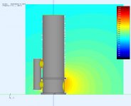
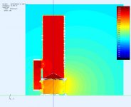
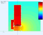
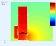
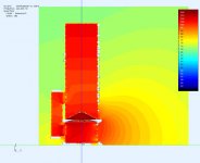
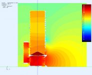
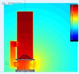
I thought it would be interesting to model this in ABEC. I had to initially guess at a few parameters so I'm not done yet. Its interesting to see how the internal pressures change with frequency. Use the pressure legend because ABEC autosolarizes each graph seperately, so not all colours are equivalent in each pic.
I've removed skin in all but the first pic. More plots coming as I fill in more model data and add the filters. Overall it looks like its working as a BP6. I should add that the woofer is driven with 1rms, so 1^2/4=0.25w (future pics will be the std 1w)and the distance to the right edge is 1m.
Attachments
Last edited:
ABEC sim
I've updated more ABEC parameters, but its not entirely accurate yet. I'm not sure what the wall impedance of a pvc pipe or a sonotube would be. I also don't know where the 2nd impedance peak went (compared to HornResp). In fairness, I'm not an expert in either tool.
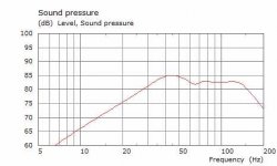
If I use pic#2 below and 80db as my end points I get 27Hz-150Hz. It could go higher, but I have a BW4@150Hz rolling off the high end. I've also increased the port#2 length to 50cm to get a flatter response. Although there is still a small bump at 45Hz that I can't explain.
It'll be interesting to compare to the actual. Parts are arriving.")
I've updated more ABEC parameters, but its not entirely accurate yet. I'm not sure what the wall impedance of a pvc pipe or a sonotube would be. I also don't know where the 2nd impedance peak went (compared to HornResp). In fairness, I'm not an expert in either tool.
If I use pic#2 below and 80db as my end points I get 27Hz-150Hz. It could go higher, but I have a BW4@150Hz rolling off the high end. I've also increased the port#2 length to 50cm to get a flatter response. Although there is still a small bump at 45Hz that I can't explain.
It'll be interesting to compare to the actual. Parts are arriving.
Attachments
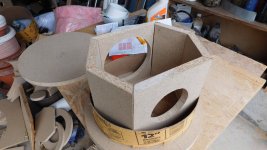
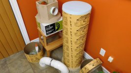
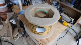
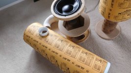
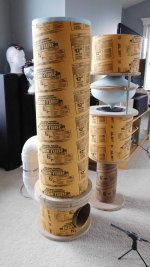
Build pics
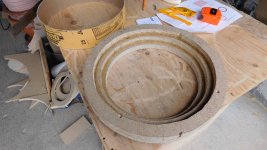
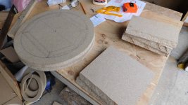
A few pics of the build in progress. It should be assembled tomorrow, and I'll start test and measurement.
The woofer throat plate will allow 8mm movement before the rubber surround touches it (Xmax is 9mm).
A few pics of the build in progress. It should be assembled tomorrow, and I'll start test and measurement.
The woofer throat plate will allow 8mm movement before the rubber surround touches it (Xmax is 9mm).
Attachments
Initial measurements
These are from a dry fit to get a first impression. There could also be minor air leaks until I chalk the seams. So far it looks good.
My class D amp board has not arrived yet, so these measurements used an additional 4ohm series resistor to raise the driver impedance for my HT amp. The 4Ohm was subtracted from the measurement in the graph.
There are peaks at 15Hz, 40Hz, and 200Hz as predicted by HornResp.
Attachments
Last edited:
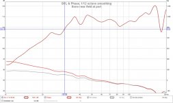
Updated - after sealing ports + fittings
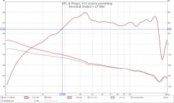
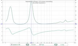
Its bolted together and sealed now. Their was some minor change and its a bit flatter.
The bump @45Hz predicted by ABEC is definitely there. I have EQ'd it out (but not posted here) to see if I could hear it, but its too early for a conclusion. I would need my amp board (still waiting) and music and listening time. So far, by using sweeps and the REW generator I'm happy with it.
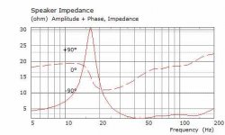
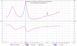
The graphs below show a -3dB point (from 125dB nearfield) of 28.5Hz which is close to the predicted and sufficient for me. The impedance peaks are in the right area (13Hz, 38Hz, 202Hz) but the two lowest peaks are not equal in height suggesting a possible tuning issue. I'll see if I can replicate this condition in HornResp or ABEC before fiddling with the physical.
Its bolted together and sealed now. Their was some minor change and its a bit flatter.
The bump @45Hz predicted by ABEC is definitely there. I have EQ'd it out (but not posted here) to see if I could hear it, but its too early for a conclusion. I would need my amp board (still waiting) and music and listening time. So far, by using sweeps and the REW generator I'm happy with it.
The graphs below show a -3dB point (from 125dB nearfield) of 28.5Hz which is close to the predicted and sufficient for me. The impedance peaks are in the right area (13Hz, 38Hz, 202Hz) but the two lowest peaks are not equal in height suggesting a possible tuning issue. I'll see if I can replicate this condition in HornResp or ABEC before fiddling with the physical.
Attachments
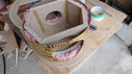
Effect of adding fiberglass fill
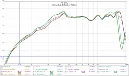
I tried adding various thickness of pink fiberglass insulation in the top (60L) V1 chamber. Mostly out of curiosity, to see if it would smooth things out or extend the FR. The fill starts at 45cm from woofer mount plane (approx midway).
Graph provided below. It does have some effect on smoothing the FR, especially at the higher end (>200Hz) which I'm not interested in. It also causes the low end to sag before 30Hz, which I'm also not interested in. This effect is like increasing the volume in HornResp. To counteract it, I would need to make the port P1 length shorter or diameter larger and it would actually extend a flat low freq roll off. Either of these changes require too much material change for a minimal benefit.
Attachments
- Status
- This old topic is closed. If you want to reopen this topic, contact a moderator using the "Report Post" button.
- Home
- Loudspeakers
- Subwoofers
- SonoTube and SewerPipe BP6 Subwoofer