Thanks, it's the first I've heard of it. I just looked up "El Pipe-O" and read the article. Great fun ")
I considered QWTL using concentric pipes to get the length in a shorter package. It always had too much ripple, so did BP8. It just looked like I could get what I needed with a BP6.
I considered QWTL using concentric pipes to get the length in a shorter package. It always had too much ripple, so did BP8. It just looked like I could get what I needed with a BP6.
Last edited:
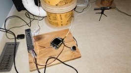
These are from a dry fit to get a first impression. There could also be minor air leaks until I chalk the seams. So far it looks good.
My class D amp board has not arrived yet, so these measurements used an additional 4ohm series resistor to raise the driver impedance for my HT amp. The 4Ohm was subtracted from the measurement in the graph.
There are peaks at 15Hz, 40Hz, and 200Hz as predicted by HornResp.
Get rid of that 4ohm resistor ASAP.
Try simulating in Hornresp what the added resistance will do. It ain't pretty.
Chris
Retested using a Class D amp
I finally got my amp and p/s and these are the near field results. Sure aa-ab31282 (200W class D) and a Qualtek QPDF-320-36 (36VDC supply, 320W).
I'm very happy with the response. I typically use a sub <=100Hz so its flat enough for me. I'm surprised at how low it goes, as I was expected a sharper drop.
Attachments
How low is required ?
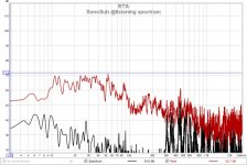
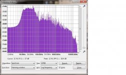
That question is asked a lot. I put on a few tracks, with low freq content, and measured with REW RTA to see what's there.
The frequencies below 20Hz cannot be heard, but they can be felt. I have a mechanical stop (throat plate) than prevents woofer from extending more than 8mm. During some of those tracks, at moderate volumes, I can hear the woofer slapping the throat plate. I need to add a HP filter @20Hz to prevent these VLFs from trashing the woofer. This is also in line with the HornResp prediction of excessive Xmax for subsonics.
Attachments
Last edited:
The cone and surround are OK, I checked them. I only use low power when testing so the force is not too great. Even so, it's enough for me to hear it. I used a spacer block to measure the surround to throat plate gap via the front port. It's actually 10mm which is already more than Xmax (9mm). I suspect the rubber surround compresses like a bumper pad to decelerate the cone.
I'm not so sure that the woofer has some built in limiter. How would you determine that?
It's only very very few tracks than have this VLF. I'll be adding a HP before the amp to prevent them in future. I was just surprised the electronics allowed them to pass.
I'm not so sure that the woofer has some built in limiter. How would you determine that?
It's only very very few tracks than have this VLF. I'll be adding a HP before the amp to prevent them in future. I was just surprised the electronics allowed them to pass.
Last edited:
Most drivers will mechanically limit before destroying themselves - they'll reach a point where the suspension will go no further, or they'll run out of motor force. That said, I did manage to fold the cone on a rather nice 15" by accidentally dumping >500w into it, way below port tuning.
Chris
Chris
I'm doing a little reading on this subject now.
It appears that Xmax is purely related to the amount of voice coil overhang and the peak travel that results in "linear" performance (ie. low distortion). Its not necessarily a physical limit like I thought.
There is another parameter "Xmech" or "Xlimit" that is the physical limit, although at the cost of much higher distortion. I can't find it for the DCS305, nor can I locate a method of measuring it (non destructively). The driver spec claims "bumped back plate" feature but does not define it.
Last edited:
...after much reading on woofer excursion
It seems the issue of exceeding safe excursion limits is fairly common for subwoofers. Many of them implement a HP filter to attenuate the subsonics.
All of the resonant designs (BR, ABC, TH, BPx) seem to have this issue for subsonic frequencies. Even a sealed box can have this issue if the box is large enough. Very few non-pro drivers have specified the Xlimit or Xmech figures, but nearly all have the Xmax. There is no clear relationship between these figures. There are many who just turn up the volume, and when you hear significant distortion, you've gone a little too far past Xmax.
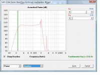
My BP6 design is reasonably well behaved and predictable displacement above 20Hz. Above 20Hz it should reach Xmax at approx 100w generating 108dB. Below 20Hz is a problem, and with just 8w @10Hz it will exceed Xmax. A 2nd order HP filter @20Hz will fix this.
It seems the issue of exceeding safe excursion limits is fairly common for subwoofers. Many of them implement a HP filter to attenuate the subsonics.
All of the resonant designs (BR, ABC, TH, BPx) seem to have this issue for subsonic frequencies. Even a sealed box can have this issue if the box is large enough. Very few non-pro drivers have specified the Xlimit or Xmech figures, but nearly all have the Xmax. There is no clear relationship between these figures. There are many who just turn up the volume, and when you hear significant distortion, you've gone a little too far past Xmax.
My BP6 design is reasonably well behaved and predictable displacement above 20Hz. Above 20Hz it should reach Xmax at approx 100w generating 108dB. Below 20Hz is a problem, and with just 8w @10Hz it will exceed Xmax. A 2nd order HP filter @20Hz will fix this.
Working with multiple subs
I connected both subs to see if I could get a flattish LF response in the listening position. Initial placement and prediction using REW.
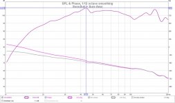
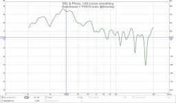
The first two graphs are the prediction and the measurement. I use Omnidirectional speakers and I have the LF at +6dB so the higher frequencies are more smoothed than predicted and the LF is raised. I also prefer a "bump" that can be EQ'd down over a "null" that can never be EQ'd out. The graphs have 1/48 octave smoothing to emphasis peaks and dips.
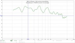
The third graph is an average (12 sample) over the listening area couch. Measurements can change alot if you move the mic and I don't always sit in the spot marked "x".
I connected both subs to see if I could get a flattish LF response in the listening position. Initial placement and prediction using REW.
The first two graphs are the prediction and the measurement. I use Omnidirectional speakers and I have the LF at +6dB so the higher frequencies are more smoothed than predicted and the LF is raised. I also prefer a "bump" that can be EQ'd down over a "null" that can never be EQ'd out. The graphs have 1/48 octave smoothing to emphasis peaks and dips.
The third graph is an average (12 sample) over the listening area couch. Measurements can change alot if you move the mic and I don't always sit in the spot marked "x".
Attachments
Last edited:
Great project!

For finding the perfect location for your subs in smaller rooms, if prefer the crawl around and listen method after putting a sub at play at your listening position. Where it sounds good, that is a location for your sub. Often near a corner. Repeat with more subs.
The difference between the two is the 'safety zone'. Clearly audible in a reflex sub in the higher regions but not the lower, but probably a lot less audible in a bandpass sub. Don't push itI'm doing a little reading on this subject now.
It appears that Xmax is purely related to the amount of voice coil overhang and the peak travel that results in "linear" performance (ie. low distortion). Its not necessarily a physical limit like I thought.
There is another parameter "Xmech" or "Xlimit" that is the physical limit, although at the cost of much higher distortion. ......
For finding the perfect location for your subs in smaller rooms, if prefer the crawl around and listen method after putting a sub at play at your listening position. Where it sounds good, that is a location for your sub. Often near a corner. Repeat with more subs.
HP filter added
At VLF the woofer excursions are excessive and possibly damaging and of limited value acoustically. So I added a highpass (HP) to the input of the amplifier.
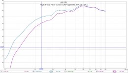
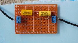
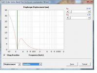
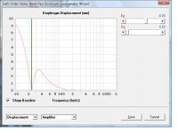
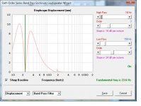
The HP filter below (pic#1) has one filter at 16Hz, and a second filter at 23Hz. Its just a couple of cascaded RC's (2 poles or 2nd order). Together they create a gentle rolloff with calc'd Fc=19Hz (-3dB). The 2nd pic (graph#1) compares the response with and without the filter. It behaves as expected. I have level shifted the filtered version up 1.5dB due to insertion loss in order to compare the curves.
As shown in graph#2, I can apply approx 100W before exceeding Xmax at 35Hz . This is from HornResp, but notice the problem for VLF displacement.
At 10Hz I have approx -15dB attn or just 18% of the VLF signal passes. Graph#3 show the max displacement, without a filter, is reached with only 9W. That is a problem. With the filter you could apply a signal equivalent to 9/0.18=50W and before reaching Xmax @10Hz. Still not perfect but its much better. More attenuation would require another filter (3rd order) and add another -6db or allow only 8% of VLF @10Hz would pass.
So far it seems like its enough. More listening is required
At VLF the woofer excursions are excessive and possibly damaging and of limited value acoustically. So I added a highpass (HP) to the input of the amplifier.
The HP filter below (pic#1) has one filter at 16Hz, and a second filter at 23Hz. Its just a couple of cascaded RC's (2 poles or 2nd order). Together they create a gentle rolloff with calc'd Fc=19Hz (-3dB). The 2nd pic (graph#1) compares the response with and without the filter. It behaves as expected. I have level shifted the filtered version up 1.5dB due to insertion loss in order to compare the curves.
As shown in graph#2, I can apply approx 100W before exceeding Xmax at 35Hz . This is from HornResp, but notice the problem for VLF displacement.
At 10Hz I have approx -15dB attn or just 18% of the VLF signal passes. Graph#3 show the max displacement, without a filter, is reached with only 9W. That is a problem. With the filter you could apply a signal equivalent to 9/0.18=50W and before reaching Xmax @10Hz. Still not perfect but its much better. More attenuation would require another filter (3rd order) and add another -6db or allow only 8% of VLF @10Hz would pass.
So far it seems like its enough. More listening is required
Attachments
I can now play this safely..
The HP filter and woofer excursion issue was from a problem playing this file (Mannheim SteamRoller, Fresh Aire 8, Big Bang). It has a lot of VLF and was causing the sub problems in an area that's not audible. It can be felt though. Still sounds the same without the woofer thrashing about at 10Hz.
The HP filter and woofer excursion issue was from a problem playing this file (Mannheim SteamRoller, Fresh Aire 8, Big Bang). It has a lot of VLF and was causing the sub problems in an area that's not audible. It can be felt though. Still sounds the same without the woofer thrashing about at 10Hz.
Attachments
HPF changes and max power estimate
I adjusted the input filters to 2nd order @16Hz, and discovered the amp also has a HPF in the 20Hz region. Sure Electronics is not specific about it, but it gives me a 3rd order HPF.
Re-running a few numbers in HornResp and verifying the approx displacement (min/max) vs freq using REW's generator. It now appears that I can drive the system with about 80W before exceeding Xmax and touching the throat plate. At that power level I get about 106dB, which I think is enough. If its not enough power, I can add a spacer and get more X-travel at the expense of increased distortion. The 200W amp I have can actually supply 155W with this driver.
Attachments
BW, EQ and distortion
I did a few more measurements with the HPF filter changes.
I also added a couple of steel band gear clamps (used 2x6" to form a 1x12") to strengthen the seal at both ends of the upper sonotube.
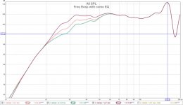
Graph#1 shows a few levels of EQ when I tried boosting the 30Hz knee to flatten out the FR. It looks better graphically, but it's only a near field measurement and the room response matters more. I need to do some listening to see if I prefer one curve over the other.
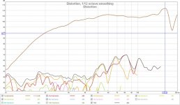
Graph#2 shows the distortion at -45dB up to about 45Hz, but then starts to rise to -35dB at 80Hz. I'm not sure if this is a problem or not and whats causing it. I don't seem to notice it and I typically roll off at 80-100Hz anyways.
I did a few more measurements with the HPF filter changes.
I also added a couple of steel band gear clamps (used 2x6" to form a 1x12") to strengthen the seal at both ends of the upper sonotube.
Graph#1 shows a few levels of EQ when I tried boosting the 30Hz knee to flatten out the FR. It looks better graphically, but it's only a near field measurement and the room response matters more. I need to do some listening to see if I prefer one curve over the other.
Graph#2 shows the distortion at -45dB up to about 45Hz, but then starts to rise to -35dB at 80Hz. I'm not sure if this is a problem or not and whats causing it. I don't seem to notice it and I typically roll off at 80-100Hz anyways.
Attachments
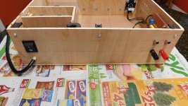
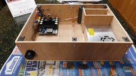
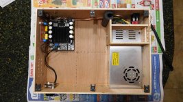
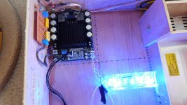
Amplifier box
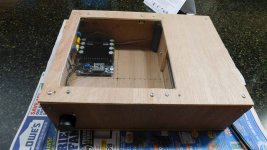
I'm not using a standard plate amp, so my collection of parts needed a box.
I have some spare sureply that's light and easy to work with. This is the first class D amp I've used and I like it, so I'm willing to try more of them. The box has room for 3 more Sure Class D amp boards that will eventually be used to bi-amp my omni speakers. I'll add more RCA jacks, speaker posts, and volume controls as the other amp boards are added.
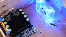
Cooling is provided by dual purposing the power supply's fan. An intake plenum on the right side and output vents on the left side. I checked with a candle and it's definitely moving air across the case as intended. The p/s fan is not as quiet as I'd like and will be replaced/modified eventually.
A plexiglass window in the lid is used view the amp status LEDs.
I'm not using a standard plate amp, so my collection of parts needed a box.
I have some spare sureply that's light and easy to work with. This is the first class D amp I've used and I like it, so I'm willing to try more of them. The box has room for 3 more Sure Class D amp boards that will eventually be used to bi-amp my omni speakers. I'll add more RCA jacks, speaker posts, and volume controls as the other amp boards are added.
Cooling is provided by dual purposing the power supply's fan. An intake plenum on the right side and output vents on the left side. I checked with a candle and it's definitely moving air across the case as intended. The p/s fan is not as quiet as I'd like and will be replaced/modified eventually.
A plexiglass window in the lid is used view the amp status LEDs.
Attachments
Sure AA-AB31282 where is that fan control ?
The spec for this amp says it has "optional fan control". When I try to get information from Sure, they tell me it has no fan ? When I ask on Parts Express I also get "there is no fan connector".
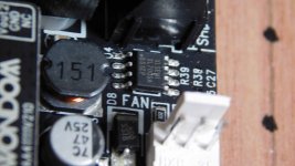
So I thought I post how to use optional the fan control, because I want to replace the power supply fan and possible just use a lower speed quieter case fan. The board has a connector labelled "fan". It's the standard 3 pin connector used on PCs. In the pic below the pins are (3=tach=left, 2=pwr=middle, 1=gnd=right).
The board uses an XL7005A buck converter (pic#1) to get +12VDC from the +36VDC input. The circuit is nearly right off the datasheet. There is a snubber diode across pin#1 and #2 to prevent negative back emf when the fan is shut off. The current capacity (see datasheet) depends on the input voltage however 200mA seems possible. The +12VDC is always running in case you want to use it for something else.
Option#1 : If you want to use the temperature based control, pin#1 will be connected to gnd only when Temp>=50C completing the circuit and turning the fan on. You can attach a small std 3-pin fan this way (pic#2).
Option#2 : If you want the fan continuously on, you can just connect the fan's pin#1 to gnd seperately (shown) Luckily, there is another nearby terminal block (shutdown) that has a gnd connection. In this configuration the fan continuously from the amp board (pic#3).
The spec for this amp says it has "optional fan control". When I try to get information from Sure, they tell me it has no fan ? When I ask on Parts Express I also get "there is no fan connector".
So I thought I post how to use optional the fan control, because I want to replace the power supply fan and possible just use a lower speed quieter case fan. The board has a connector labelled "fan". It's the standard 3 pin connector used on PCs. In the pic below the pins are (3=tach=left, 2=pwr=middle, 1=gnd=right).
The board uses an XL7005A buck converter (pic#1) to get +12VDC from the +36VDC input. The circuit is nearly right off the datasheet. There is a snubber diode across pin#1 and #2 to prevent negative back emf when the fan is shut off. The current capacity (see datasheet) depends on the input voltage however 200mA seems possible. The +12VDC is always running in case you want to use it for something else.
Option#1 : If you want to use the temperature based control, pin#1 will be connected to gnd only when Temp>=50C completing the circuit and turning the fan on. You can attach a small std 3-pin fan this way (pic#2).
Option#2 : If you want the fan continuously on, you can just connect the fan's pin#1 to gnd seperately (shown) Luckily, there is another nearby terminal block (shutdown) that has a gnd connection. In this configuration the fan continuously from the amp board (pic#3).
Attachments
- Status
- This old topic is closed. If you want to reopen this topic, contact a moderator using the "Report Post" button.
- Home
- Loudspeakers
- Subwoofers
- SonoTube and SewerPipe BP6 Subwoofer