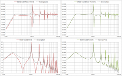
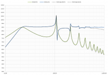
Comparing an Identical driver/data etc with Dayton Audio RSS265HO*4 between WinISD v0.7.0.950 & HR v39.90 sims, essentially all the results were very similar, with ONE exception, which i hadn't noticed before !
HornResponse simmed with no masking of enclosure resonances. WInISD simmed with "transmission line"-model for port simulation.
See the difference between the graphs ! Is the the reason HornResponse is showing just the enclosure resonaces & WInISD just showing the port harmonic resonances ?
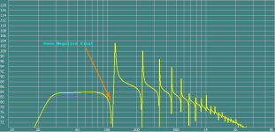
HornResponse simmed with no masking of enclosure resonances. WInISD simmed with "transmission line"-model for port simulation.
See the difference between the graphs ! Is the the reason HornResponse is showing just the enclosure resonaces & WInISD just showing the port harmonic resonances ?
Attachments
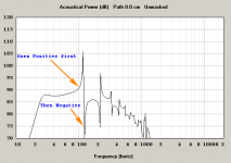
Is the the reason HornResponse is showing just the enclosure resonaces
Hornresp is showing both the enclosure and port resonances.
(This can be readily confirmed by altering the Lrc and Lpt slider settings in the Loudspeaker Wizard and observing the effect on the combined response).
Comparing an Identical driver/data etc with Dayton Audio RSS265HO*4 between WinISD v0.7.0.950 & HR v39.90 sims, essentially all the results were very similar, with ONE exception, which i hadn't noticed before !
HornResponse simmed with no masking of enclosure resonances. WInISD simmed with "transmission line"-model for port simulation.
See the difference between the graphs ! Is the the reason HornResponse is showing just the enclosure resonaces & WInISD just showing the port harmonic resonances ?
Adjust the offset between the driver and the vent in HornResp to see if those differences change
")
@ David McBean
I find it interesting that the major difference between the two program graphs, are the inverted rising/falling points, inbetween the others ! It's those differences that i'd like to know the reason for ?
@ Brian Steele
The harmonics do change with both programs, but that's not what i'm wondering about.
But, please explain the reason for the differences shown for the positive going responses versus the negative going responses, between both programs ?
I have no idea why the WinISD combined response results should be different to those generated by Hornresp. They look suspiciously 'neat' to me, so perhaps there is some simplification of the port 'transmission line' model somewhere. The Hornresp combined power response results are consistent with those produced by AkAbak, and by a simulation program developed by Dr Bjørn Kolbrek to assist with his horn loudspeaker research.
How do the non-combined separate outputs from the driver and the port compare in WinISD and Hornresp?
Last edited:

Hi Zero D,
I did not interpret your comments that way either, but felt that it was worth comparing the Hornresp results against those of other simulation programs, to confirm that the HR model was indeed operating correctly.
Incidentally, I have no problem with people criticizing Hornresp - such feedback is extremely useful, and can result in significant improvements being made to the program.
I have tried everything I can think of in an attempt to reproduce the WinISD results in Hornresp (by modifying the code) but I can't even get close. There appears to be something not quite right with the WinISD transmission line model, but what it is, remains a mystery. Only the authors of the program would know what they have done.
Kind regards,
David
I was & am not critisizing HR
I did not interpret your comments that way either, but felt that it was worth comparing the Hornresp results against those of other simulation programs, to confirm that the HR model was indeed operating correctly
.Incidentally, I have no problem with people criticizing Hornresp - such feedback is extremely useful, and can result in significant improvements being made to the program.
just trying to discover why they differ re the Pos V Neg areas ?
I have tried everything I can think of in an attempt to reproduce the WinISD results in Hornresp (by modifying the code) but I can't even get close. There appears to be something not quite right with the WinISD transmission line model, but what it is, remains a mystery. Only the authors of the program would know what they have done
.Kind regards,
David
I wonder if it is not the line model that is the issue, but a simplification of the radiation impedance applied at the port opening.....There appears to be something not quite right with the WinISD transmission line model, but what it is, remains a mystery...
@Zero D,
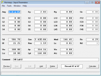
Can you post a pic of the Hornresp inputs used to produce your plot in post#1?
@ David McBean
Glad you didn't take it the wrong way, & that you appreciate comments/input etc
Jeepers, i didn't expect you to spend a lot of time on this, but Thanx for checking etc etc I've tried to email the authors of WinISD a number of times over the years, to encourage them to keep updating it etc. Well they have several times, but i Never got an email back
Hmm, good point, i don't know !
I just tried to recreate the sim for you to post, as unfortunately i didn't save it earlier, but i forgot the details i simmed before
It's actually the RSS265HF*4 10" Reference HF Subwoofer 4 Ohm i simmed, not the RSS265HO 4 as mentioned before
Glad you didn't take it the wrong way, & that you appreciate comments/input etc
Jeepers, i didn't expect you to spend a lot of time on this, but Thanx for checking etc etc
I've tried to email the authors of WinISD a number of times over the years, to encourage them to keep updating it etc. Well they have several times, but i Never got an email back Originally Posted by bolserst
I wonder if it is not the line model that is the issue, but a simplification of the radiation impedance applied at the port opening.
Hmm, good point, i don't know !
I just tried to recreate the sim for you to post, as unfortunately i didn't save it earlier, but i forgot the details i simmed before
It's actually the RSS265HF*4 10" Reference HF Subwoofer 4 Ohm i simmed, not the RSS265HO 4 as mentioned before
I stumbled on a white paper(attached) on the box modeling approach used for WinISD here:
http://jahonen.kapsi.fi/Audio/Papers/enclosuremodelling.pdf
Scanning the equations used for modeling the port of a vented enclosure, it suddenly came to me what was wrong with the WinISD “transmission line” port model. In simplest terms, WinISD is basing the acoustic output of the port on the volume velocity “ENTERING” the port from the enclosure side. Hornresp bases the port output on the volume velocity “EXITING” the port to the listening room. The assumption is that the air in the port is acting like an ideal lumped mass moving in and out of the port in perfect unison. In actuality, when the wavelength of sound gets smaller than the length of the port, this is not a good assumption since air has properties of both mass and compliance. Both magnitude and phase between entrance and exit will be different.
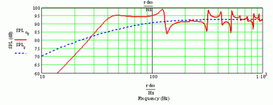
For an example, I used a LAB12 driver in a 100L enclosure tuned to ~23Hz with a 1.6m long port 20cm in diameter. Voice coil inductance was ignored.
Pic #1: Spice modeling comparison of the WinISD lumped and transmission line port modeling.
- Blue curve is the volume velocity thru the port modeled as a lumped mass
- Red curve is the volume velocity entering the TL port model
- Green curve is the volume velocity exiting the TL port model
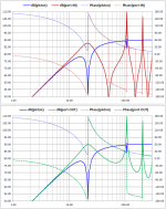
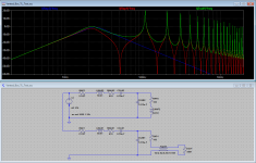
Pic #2: Time to do an apples-to-apples comparison with Hornresp; here are the inputs.
Pic #3: Port and Piston+Port comparisons with Hornresp.
- Left side comparison plots are using the volume velocity entering the TL port model
- Right side comparison plots are using the volume velocity exiting the TL port model
It is easy to see that using the volume velocity exiting the TL port provides a satisfying match with Hornresp. The differences in the amplitude of the peaks at higher frequencies are due to the simplified port model used by WinISD. Looking at equation (41) in the white paper, the port is modeled as an open ended tube. If radiation impedance(airload) at the port exit was included, the match would be even better…but probably unnecessarily complicated considering the purpose of WinISD.
Pic #4: Plots showing piston and port magnitude and phase. Looking at the phase just before and after the first peak(~110Hz) you can understand why the WinISD plots were showing a "dip-peak" while Hornresp was showing a "peak-dip".
For a constant cross-section port, there is a simple two term equation to calculate the port exit volume velocity from the port entrance volume velocity. I will email the author of the white paper to see if there might be interest in updating WinISD with this improvement.
http://jahonen.kapsi.fi/Audio/Papers/enclosuremodelling.pdf
Scanning the equations used for modeling the port of a vented enclosure, it suddenly came to me what was wrong with the WinISD “transmission line” port model. In simplest terms, WinISD is basing the acoustic output of the port on the volume velocity “ENTERING” the port from the enclosure side. Hornresp bases the port output on the volume velocity “EXITING” the port to the listening room. The assumption is that the air in the port is acting like an ideal lumped mass moving in and out of the port in perfect unison. In actuality, when the wavelength of sound gets smaller than the length of the port, this is not a good assumption since air has properties of both mass and compliance. Both magnitude and phase between entrance and exit will be different.
For an example, I used a LAB12 driver in a 100L enclosure tuned to ~23Hz with a 1.6m long port 20cm in diameter. Voice coil inductance was ignored.
Pic #1: Spice modeling comparison of the WinISD lumped and transmission line port modeling.
- Blue curve is the volume velocity thru the port modeled as a lumped mass
- Red curve is the volume velocity entering the TL port model
- Green curve is the volume velocity exiting the TL port model
Pic #2: Time to do an apples-to-apples comparison with Hornresp; here are the inputs.
Pic #3: Port and Piston+Port comparisons with Hornresp.
- Left side comparison plots are using the volume velocity entering the TL port model
- Right side comparison plots are using the volume velocity exiting the TL port model
It is easy to see that using the volume velocity exiting the TL port provides a satisfying match with Hornresp. The differences in the amplitude of the peaks at higher frequencies are due to the simplified port model used by WinISD. Looking at equation (41) in the white paper, the port is modeled as an open ended tube. If radiation impedance(airload) at the port exit was included, the match would be even better…but probably unnecessarily complicated considering the purpose of WinISD.
Pic #4: Plots showing piston and port magnitude and phase. Looking at the phase just before and after the first peak(~110Hz) you can understand why the WinISD plots were showing a "dip-peak" while Hornresp was showing a "peak-dip".
For a constant cross-section port, there is a simple two term equation to calculate the port exit volume velocity from the port entrance volume velocity. I will email the author of the white paper to see if there might be interest in updating WinISD with this improvement.
Attachments
Scanning the equations used for modeling the port of a vented enclosure, it suddenly came to me what was wrong with the WinISD “transmission line” port model.
Hi bolserst,
Once again, brilliant work on your part! A very thorough and beautifully documented analysis. Many thanks for solving the mystery for us
.Kind regards,
David
Glad to have finally figured it out. It just popped in my head while I was reading the white paper. I had previously noticed similar port responses in the UniBox modeling software and had always intended to try and figure out what was going on.Many thanks for solving the mystery for us
Yup, it's the odd multiples of 1/4 wave resonance where the differences show up....Interestingly, apart from the discrepancy, most plots line up in the same positions.
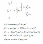
Just for grins I tried adding the simplified radiation impedance model from Beranek/Leach to the end of the port to see how well it would clear up the remaining discrepancies. Survey says....surprisingly well, for such a simple model.
Attachments
I will email the author of the white paper to see if there might be interest in updating WinISD with this improvement.
I have been very quiet with WinISD calculation stuff on recent years but I still can certainly do changes to the math if I just figure out what exactly needs to be done. But however, actual releases have been done by main author Juha, so I can't really promise when that would be available after I get satisfactory results.
Regards,
Janne
@ bolserst
Thanx for the extra model
@ jahonen
Great to see you posting after a Long time If you could get Juha to modify the code, that would be Very helpful. WinISD was my first experience with such software, which enabled me to learn a lot more, & successfully design & build many nice systems. So i have a soft spot for it
Thanx for the extra model
@ jahonen
Great to see you posting after a Long time
If you could get Juha to modify the code, that would be Very helpful. WinISD was my first experience with such software, which enabled me to learn a lot more, & successfully design & build many nice systems. So i have a soft spot for it - Status
- This old topic is closed. If you want to reopen this topic, contact a moderator using the "Report Post" button.
- Home
- Loudspeakers
- Subwoofers
- Discrepancy between WinISD & HornResponse