Does look attractively wicked! yes =) now have a look at this
I do like the wicked aesthetic , although not an entirely efficient use of space .. .
BP1Fanatic, you might appreciate the following sub for car audio:
These Twisted Sounds drivers are very capable for the price (assuming their published figures are accurate) ... I was able to get two of the 12s to work in a 400 liter box that is like Mario's Super Planar (same internal volume, same tuning , same CSAs and path lengths)
That 1st enclosure looks wicked!
I do like the wicked aesthetic
, although not an entirely efficient use of space .. .BP1Fanatic, you might appreciate the following sub for car audio:
These Twisted Sounds drivers are very capable for the price (assuming their published figures are accurate) ... I was able to get two of the 12s to work in a 400 liter box that is like Mario's Super Planar (same internal volume, same tuning , same CSAs and path lengths)
Last edited:
Can do =D
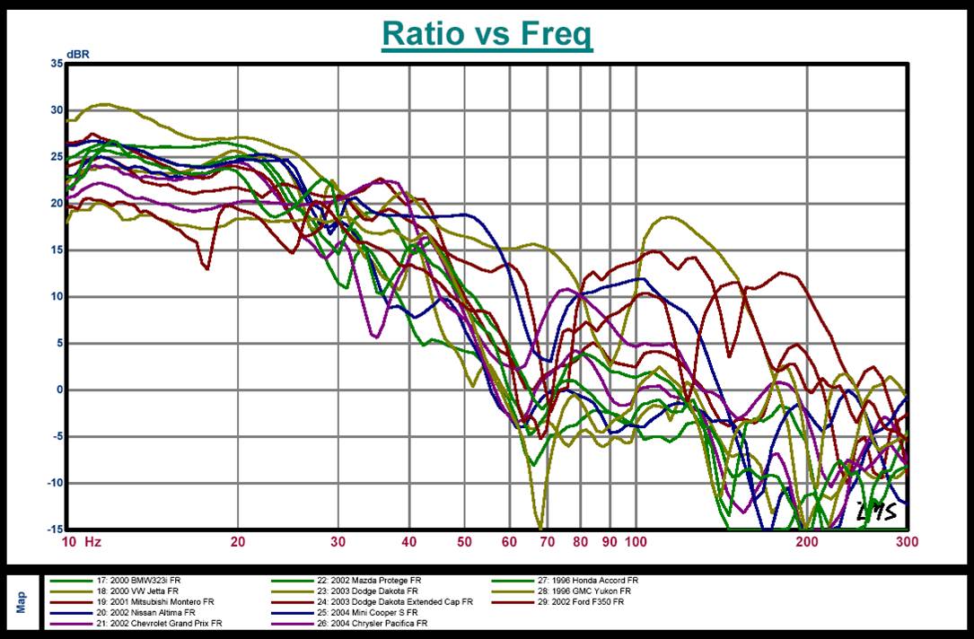
I could see how that would be beneficial when trying to flatten in-vehicle response if you are trying to work around a vehicle's cabin resonance bump centered around 60hz
Well, I have good news for you USRFobiwan!
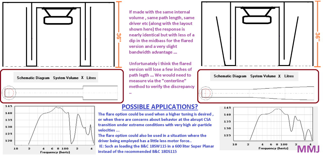
Fortunately what you ask is easy to do with this design, it is just matter of changing the dimensions of the latter portion of the main path (reducing the ratio of expansion) in order to tune our middle resonance higher (while also also tuning the front chamber upward by the same amount) ...... We are juggling two resonances up in that range .. .....
As a bonus: The process of moving that big mountain of efficiency upward allows me to reduce the path length and cabinet size while maintaining the same fundamental tuning
I'd prefer to have the peak between 80-100hz.
I could see how that would be beneficial when trying to flatten in-vehicle response if you are trying to work around a vehicle's cabin resonance bump centered around 60hz
Well, I have good news for you USRFobiwan!
Fortunately what you ask is easy to do with this design, it is just matter of changing the dimensions of the latter portion of the main path (reducing the ratio of expansion) in order to tune our middle resonance higher (while also also tuning the front chamber upward by the same amount) ...... We are juggling two resonances up in that range .. .....
As a bonus: The process of moving that big mountain of efficiency upward allows me to reduce the path length and cabinet size while maintaining the same fundamental tuning
Working around cabinet gain
I am not really a Car Audio guy but it has been fun getting to know some lately .....
Here are the cabin gain curves that Just A Guy posted in #282 ..............
If someone knew what curve their cabin produces then we could strategically place the Super Planar's response hump to get the results you desire (SPL or SQ right?) .....
Just a thought ...
If someone knew what curve their cabin produces then we could strategically place the Super Planar's response hump to get the results you desire (SPL or SQ right?) .....
... meanwhile, back in the real world.....
There are lots of ways in which the anechoic speaker or sim-world response differs from sound in a room or car. Just adds to the confusion and misdirection to lump them under the term "cabin gain".
One way sound is different is by pressure build-up in small tightly sealed spaces. In rooms, this is a trivial and mostly sub-sonic (if at all). But pressure build-up can be present in a sealed car with solid walls esp if you remember to put your A/C source on "recirculate" and roll up the windows tight*.
In a room made with the usual stud-and-drywall construction, the factors of greater importance are reflection modes and how furnishings influence the modes. These are conditioned by the SPECIFIC location of the speaker and the listener. I recently posted examples of room effects for two subs (in different locations, of course, but just a single listener location) and they sure look different.
Subs in rooms, some data points
Matthew is right to think you need to take the environment of the car or room into account. Just designing the perfect speaker gets you only part of the way there.
But the influence of the environment isn't something you can dial-in ahead of doing relevant measurements in-situ.
B.
*especially if I am standing next to you at a stoplight
Last edited:
Many factors ..
Bentoronto,
Correct .....
The cabinet's position and listener's position , along with room reflection/modes , furniture etc ........
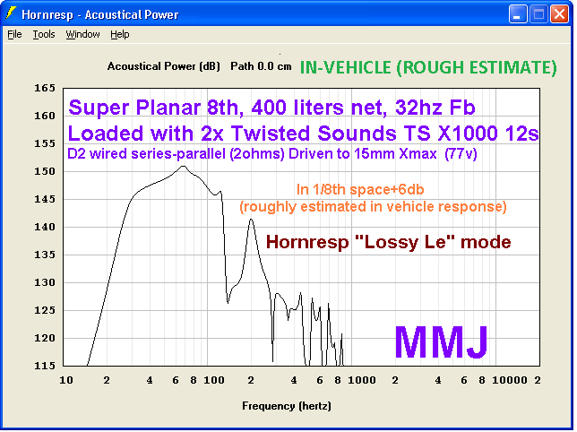
I can't expect to take everything into account within a Hornresp simulation, but i can get partway there at least (roughly) in the case of a vehicle's cabin , but that is still only an approximation at best ..
So far with the two different Super Planar 8th (compound BLH/RLH stepped) cabinets that we have in real-world vehicles the owners seem to be measuring an output that is around what we see in Hornresp when used in 1/8th space+6db , but i don't expect that to be the same in every vehicle .. .
In a room made with the usual stud-and-drywall construction, the factors of greater importance are reflection modes and how furnishings influence the modes. These are conditioned by the SPECIFIC location of the speaker and the listener. I recently posted examples of room effects for two subs (in different locations, of course, but just a single listener location) and they sure look different.
Subs in rooms, some data points
Matthew is right to think you need to take the environment of the car or room into account. Just designing the perfect speaker gets you only part of the way there.
But the influence of the environment isn't something you can dial-in ahead of doing relevant measurements in-situ.
B.
*especially if I am standing next to you at a stoplight
Bentoronto,
Correct .....
The cabinet's position and listener's position , along with room reflection/modes , furniture etc ........
I can't expect to take everything into account within a Hornresp simulation, but i can get partway there at least (roughly) in the case of a vehicle's cabin , but that is still only an approximation at best ..
So far with the two different Super Planar 8th (compound BLH/RLH stepped) cabinets that we have in real-world vehicles the owners seem to be measuring an output that is around what we see in Hornresp when used in 1/8th space+6db , but i don't expect that to be the same in every vehicle .. .


This is also an option.
Obi ,
Good one!
I will save this in my collection of fold options..It is good to have a lot of fold or layout options that we can to turn to... Makes it easier to find a fold that fits the path length and dimension requirements of a project when you have so many options to choose from.
..... Procedure
When modeling one of these Compound RLH/BLH designs in Hornresp the secret is to stagger the resonances in the right order and with fairly even spacing ... I will provide an example below...
If we are wanting a subwoofer cabinet with a tuning in the mid 30s there will be another strong resonance that falls in the 65hz to 75hz range as long as we have provided enough expansion in the main path (some believe this is a separate quarterwave resonance but it may also just be the Fb*3 harmonic shoved downward into our working range and made prominent due the path's expansion, either way it is very useful to us) ............................................. Next we want to tune the length of the short resonator, and i am referring to the resonator in which our driver's motor is located (in the above sketch)... This resonator is what i call the front chamber (but is referred to as the "rear vented" chamber in Hornresp) .... Adjust the length of that resonator (i adjust "Lpt" in my models for this) so that this resonance lands right between our 70hz-ish resonance mentioned previously and the next odd harmonic up (Fb*5 shifted down) which will usually end up right around the vicinity of 115 to 130hz so we should tune our front chamber to around 90hz to 100hz ... Perform this fine tuning in Halfspace (2pi) and using either the impedance graph zoomed in or the "Diaphagm Displacement" (cone excursion) graph you should be able to easily see what is going on with the dips corresponding to our resonances. 

So if all goes well we could end up with resonances at 35hz, 70hz, 90hz, 120hz .....
The first three resonances are most important as they are all at play well within our working range ..... Output up around 120hz is generally not as strong (in sim) especially with multiple cabinets or additional boundary gain, and the midbass response hole is located just above that harmonic ....
This is also an option.
When modeling one of these Compound RLH/BLH designs in Hornresp the secret is to stagger the resonances in the right order and with fairly even spacing ... I will provide an example below...
If we are wanting a subwoofer cabinet with a tuning in the mid 30s there will be another strong resonance that falls in the 65hz to 75hz range as long as we have provided enough expansion in the main path (some believe this is a separate quarterwave resonance but it may also just be the Fb*3 harmonic shoved downward into our working range and made prominent due the path's expansion, either way it is very useful to us
) ............................................. Next we want to tune the length of the short resonator, and i am referring to the resonator in which our driver's motor is located (in the above sketch)... This resonator is what i call the front chamber (but is referred to as the "rear vented" chamber in Hornresp) .... Adjust the length of that resonator (i adjust "Lpt" in my models for this) so that this resonance lands right between our 70hz-ish resonance mentioned previously and the next odd harmonic up (Fb*5 shifted down) which will usually end up right around the vicinity of 115 to 130hz so we should tune our front chamber to around 90hz to 100hz ... Perform this fine tuning in Halfspace (2pi) and using either the impedance graph zoomed in or the "Diaphagm Displacement" (cone excursion) graph you should be able to easily see what is going on with the dips corresponding to our resonances. So if all goes well we could end up with resonances at 35hz, 70hz, 90hz, 120hz .....
The first three resonances are most important as they are all at play well within our working range ..... Output up around 120hz is generally not as strong (in sim) especially with multiple cabinets or additional boundary gain, and the midbass response hole is located just above that harmonic ....
Now for something truly extreme
For fun , and just to see if it would work (in sim) ...
I made this cabinet a little larger than necessary in an attempt to eek out a little more efficiency ...
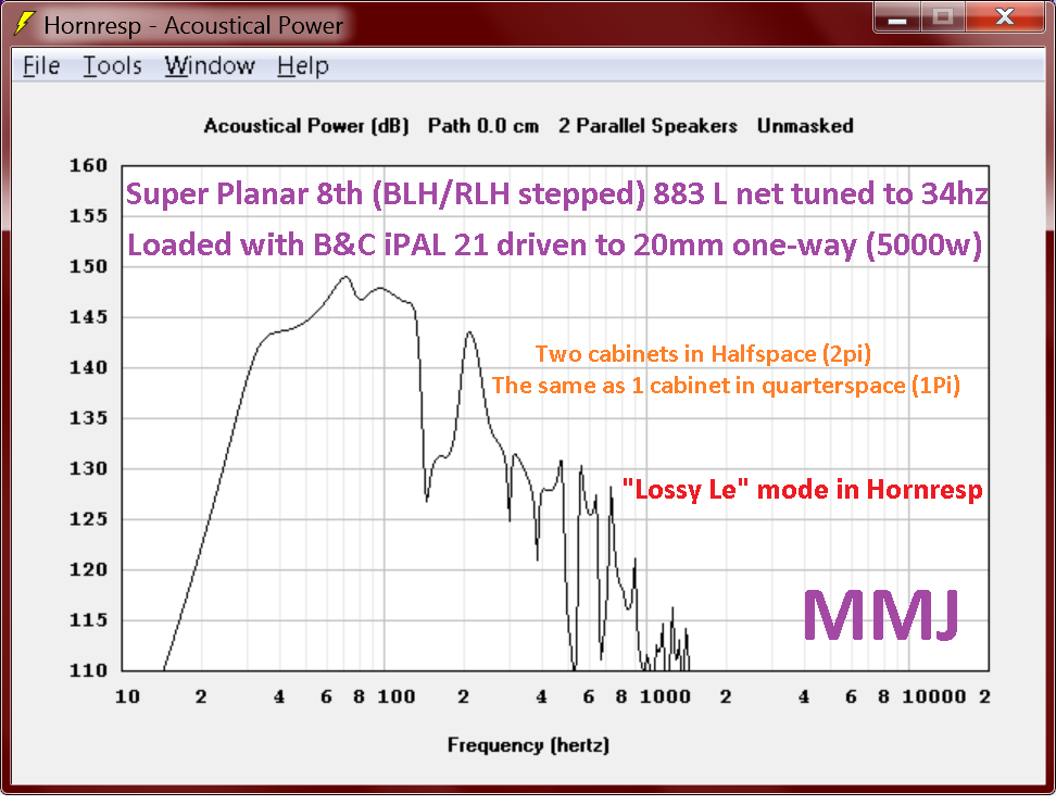
We are dumping 5000 watts into this iPAL and it is just starting to approach Xmax .... The rating is 22mm and we are hitting 20mm at 5000w ...
This is a lot of pressure for a 21" cone ... I wonder if it would survive?
This is a cool novelty and all but honestly two of the Super Planar 8th 600 liter cabinets (1200 liter total) loaded with the 18DS115 at 3400 watts for the pair do just as well as a single iPAL 21 cabinet (883 liters as featured here) at 5000 watts ....... The curve is almost an exact match in fact ....
The two 18DS115s cost less , but two of them do require more cabinet volume than the single iPAL ...
For fun , and just to see if it would work (in sim) ...
I made this cabinet a little larger than necessary in an attempt to eek out a little more efficiency ...
We are dumping 5000 watts into this iPAL and it is just starting to approach Xmax .... The rating is 22mm and we are hitting 20mm at 5000w ...
This is a lot of pressure for a 21" cone ... I wonder if it would survive?
This is a cool novelty and all but honestly two of the Super Planar 8th 600 liter cabinets (1200 liter total) loaded with the 18DS115 at 3400 watts for the pair do just as well as a single iPAL 21 cabinet (883 liters as featured here) at 5000 watts ....... The curve is almost an exact match in fact ....
The two 18DS115s cost less , but two of them do require more cabinet volume than the single iPAL ...
Here you go!
Here it is BPIFan
As requested
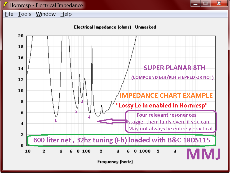
Where is the impedance curve to show the multiple resonances?
Here it is BPIFan
As requested
Gladly
No problem guys!
As you can see in my example given at post #355 the fundamental resonance and the next resonance up (labeled #2 in the chart) have a relatively wide-ish spread, which is directly related to the expansion in the main path... I mentioned that it is not always practical to have perfectly even spacing and this one of those situations ............ If the designer wanted to reduce the spacing between #1 and #2 (referring to the chart) we can accomplish this by either increasing the cross sectional area of the large portion of the main path in relation to the slender portion of the main path , or lengthening (deepening) the large CSA portion of the main path .. . Either method works, and a combination also works .. ...... It is the same as increasing the expansion rate on a large horn , we are just making the expansion happen in one abrupt step here , that's all ..
Johannes and Martinsson were using a 1:3 CSA ratio with a "resonator" depth upwards of 90cm-ish which is a good way to go ....... I was able to get up to a 1:2.4 ratio with the 18DS115 cabinet used in our example if I stick with the 24" x 54" x 36" dimensions, this is due to the 18" driver eating up so much width (in this fold style)...Going with dual 12s would have allowed me to get closer to a 1:3 ratio in these dimensions + a little extra height (so the 12" drivers could fit one over the other) .... OR if i were to change the outer dimensions i could have also nailed that 1:3 with the 18 .. ............. Nevertheless , not a big deal, this combination of driver and cabinet is a fully marvelous performer with the resonance spacings just as they are ... .
With even higher ratios we increase the efficiency but that comes at the cost of a larger cabinet and we are also sacrificing some bandwidth in the process ....... Choose your compromises wisely
NOTE: The loss in bandwidth doesn't necessarily apply to the wideband kickbin horn versions of this cabinet, but that is whole other tuning and scale.... The first Super Planar tops that we made had expansion in the main path (not stepped) and they produced a fantastic amount of bandwidth , i sometimes refer to these ones as the 3-way "Club Tops" , although i know now that we could have easily made them 2-way ....They are featured in post #1 of this discussion........ The "spanned" driver-offsets in this design probably played a role in smoothing the midbass and lower midrange response ...
very interesting! thanks for explaining MMJ.
+2! Very interesting
No problem guys!
As you can see in my example given at post #355 the fundamental resonance and the next resonance up (labeled #2 in the chart) have a relatively wide-ish spread, which is directly related to the expansion in the main path... I mentioned that it is not always practical to have perfectly even spacing and this one of those situations ............ If the designer wanted to reduce the spacing between #1 and #2 (referring to the chart) we can accomplish this by either increasing the cross sectional area of the large portion of the main path in relation to the slender portion of the main path , or lengthening (deepening) the large CSA portion of the main path .. . Either method works, and a combination also works .. ...... It is the same as increasing the expansion rate on a large horn , we are just making the expansion happen in one abrupt step here , that's all ..
Johannes and Martinsson were using a 1:3 CSA ratio with a "resonator" depth upwards of 90cm-ish which is a good way to go ....... I was able to get up to a 1:2.4 ratio with the 18DS115 cabinet used in our example if I stick with the 24" x 54" x 36" dimensions, this is due to the 18" driver eating up so much width (in this fold style)...Going with dual 12s would have allowed me to get closer to a 1:3 ratio in these dimensions + a little extra height (so the 12" drivers could fit one over the other) .... OR if i were to change the outer dimensions i could have also nailed that 1:3 with the 18 .. ............. Nevertheless , not a big deal, this combination of driver and cabinet is a fully marvelous performer with the resonance spacings just as they are ... .
With even higher ratios we increase the efficiency but that comes at the cost of a larger cabinet and we are also sacrificing some bandwidth in the process ....... Choose your compromises wisely
NOTE: The loss in bandwidth doesn't necessarily apply to the wideband kickbin horn versions of this cabinet, but that is whole other tuning and scale.... The first Super Planar tops that we made had expansion in the main path (not stepped) and they produced a fantastic amount of bandwidth , i sometimes refer to these ones as the 3-way "Club Tops" , although i know now that we could have easily made them 2-way ....They are featured in post #1 of this discussion........ The "spanned" driver-offsets in this design probably played a role in smoothing the midbass and lower midrange response ...
Last edited:
- Home
- Loudspeakers
- Subwoofers
- Compound loading 6th order quarterwave "Super Planar" horns and pipes concepts/builds