Resonances and exhibitionism
Zero D,
Glad you don't mind the sketch , hehe, and yes , we could call it a MLTL-DCR hybrid MTM sort of thing .....
I get a kick out of how the nomenclature in this field is still so flexible
Imagine the two impedance peaks as you would see in a bass reflex (single Helmholtz) except that the upper peak is split in two by our parasitic resonance so that we end up with three peaks now
At this point i am convinced that she has an exhibitionism fetish so i can say with confidence that she appreciates being seen as much (or more) than we appreciate seeing her!
@ Matthew Morgan J
Hi, in Post #186 your NOT "horrible old rough & ugly sketch" seems more like a MLTL-DCR hybrid to me.
Zero D,
Glad you don't mind the sketch , hehe, and yes , we could call it a MLTL-DCR hybrid MTM sort of thing .....
I get a kick out of how the nomenclature in this field is still so flexible
Ignoring the DCR part for a moment, the f high/low impedances are what we usually see in BR designs etc. So in this case, the f low impedance peak suggests to me that the MLTL part is actually tuned lower than you might have thought ! Unless, it's due to the DCR portion skewing the f high peak, & consequently the f low too ?
Imagine the two impedance peaks as you would see in a bass reflex (single Helmholtz) except that the upper peak is split in two by our parasitic resonance so that we end up with three peaks now
Always good to get another chance to see your glamorous assistant again
At this point i am convinced that she has an exhibitionism fetish so i can say with confidence that she appreciates being seen as much (or more) than we appreciate seeing her!
Yessir , that's right
Johannes,
Exactly right ... . It does improve efficiency and performance even further even though it was pretty extreme to begin with! The cabinet was already at 500 liters net as it was, so in order to avoid making it even larger I made that compromise ...
According to what Samuel was saying he plans to set these up in a domestic permanent installation sort of situation, so perhaps he wouldn't mind if we go beyond 500 liters .... I suppose i should give him some estimated outer dimensions and see how he feels about those ..
We suspect that these things might be frightfully loud in-vehicle .... We will know for sure soon enough as two of our car audio friends are planning to build Super Planar 8th order cabinets to put into their vehicle (one with high tuning for SPL competition purposes , and the other with 30hz tuning) .. Dustin made some great 3d sketches for them (maybe he will post them?)... I am looking forward to the reports ... 
you should not skimp with the cross section area of the resonators.
You gain almost 2 dB efficiency in the lower part of the passband from increasing the cross section of the resonators (grey line = your simulation - black line = my sim with a larger cross section area).
Johannes,
Exactly right ... . It does improve efficiency and performance even further even though it was pretty extreme to begin with!
The cabinet was already at 500 liters net as it was, so in order to avoid making it even larger I made that compromise ... According to what Samuel was saying he plans to set these up in a domestic permanent installation sort of situation, so perhaps he wouldn't mind if we go beyond 500 liters .... I suppose i should give him some estimated outer dimensions and see how he feels about those ..
I really like your compound horn Super Planar quarter wave thingy.... The idea of one of those in a car scares me....
Regards,
Johannes
We suspect that these things might be frightfully loud in-vehicle
.... We will know for sure soon enough as two of our car audio friends are planning to build Super Planar 8th order cabinets to put into their vehicle (one with high tuning for SPL competition purposes , and the other with 30hz tuning) .. Dustin made some great 3d sketches for them (maybe he will post them?)... I am looking forward to the reports ... I think so too =D
BP1fan,
It sure seems like it should have the potential to be a great solution for an SUV We will know more about how they behave in-vehicle here in the very near future ...
Samuel's 8th order Super Planar will be used in a different setting (at home, and possibly PA from what i gather) ....
That curve looks GREAT for car audio! I could see that enclosure looking awesome in the back of a SUV!
BP1fan,
It sure seems like it should have the potential to be a great solution for an SUV
We will know more about how they behave in-vehicle here in the very near future ...Samuel's 8th order Super Planar will be used in a different setting (at home, and possibly PA from what i gather) ....
Right , but then we recently took it to the next level ! =D
Brian Steele,
The Bose Wave Cannon is a 6th order parallel tuned compound loaded QWP design, and yes very much like the early 6th Order Super Planar subs which are featured in the latter part of post #1 in this discussion, as you can see in those build photos they were basically a folded version of such a topology ...
In these newer Super Planar variants the abrupt expansion in the main path provides us with one additional resonance within the passband to juggle and that is why i call it 8th order... ......... The cabinet is larger and more complex with the benefit of higher efficiency and increased output (assuming that what Hornresp is telling us about this arrangement is indeed accurate) .....
So there are still compromises being made but for those who don't mind some extra complexity and size (along with somewhat less bandwidth) this may turn out to be a powerful option We are still in the early stages of exploring this new variant though, some cabinets need to be built and measured, and then we will know more .....
I thought the topology of that "planar horn" looks a lot like a folded up "Bose Cannon"
Brian Steele,
The Bose Wave Cannon is a 6th order parallel tuned compound loaded QWP design, and yes very much like the early 6th Order Super Planar subs which are featured in the latter part of post #1 in this discussion, as you can see in those build photos they were basically a folded version of such a topology ...
In these newer Super Planar variants the abrupt expansion in the main path provides us with one additional resonance within the passband to juggle and that is why i call it 8th order... ......... The cabinet is larger and more complex with the benefit of higher efficiency and increased output (assuming that what Hornresp is telling us about this arrangement is indeed accurate) .....
So there are still compromises being made but for those who don't mind some extra complexity and size (along with somewhat less bandwidth) this may turn out to be a powerful option
We are still in the early stages of exploring this new variant though, some cabinets need to be built and measured, and then we will know more .....
Last edited:
Originally Posted by Matthew Morgan J
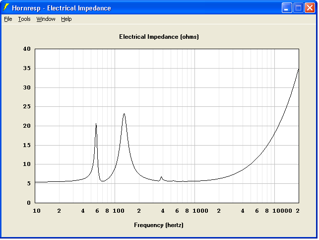
Imagine the two impedance peaks as you would see in a bass reflex (single Helmholtz) except that the upper peak is split in two by our parasitic resonance so that we end up with three peaks now
Yeah i realise that
But i was wondering about why the f-Low impedance peak is as low as it is, inspite of the design goals "front box" fb being higher than shown ? Without the extra DCR volume, eg BR/TL etc, the f-Low impedance peak should be higher. That's why i thought the fb of the "back box" might be influencing/dragging the "front box" f-High impedance higher ?
If you see what i mean ? If not i'll try to expand on it
Without the DCR back box, i might expect the impedance peak to look a "bit" like this.

You think your drawings are poor
Interesting info about your "glamorous assistant"
You lucky guy Ok, i see now ..
Zero D,
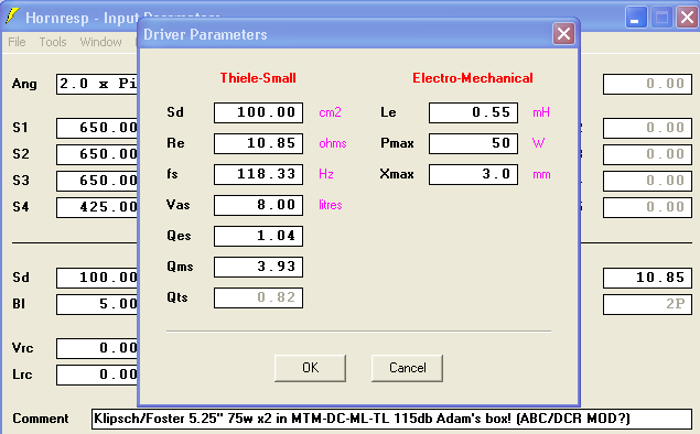
You draw much like i do , hehehe , but it works and yes i can see what you mean now ..... So i brought up a 42" QWP (TL) model in Hornresp with dual offset budget drivers (they are Klipsch/Foster 5.25" woofs)......So this is a simulation of the cabinet without the DCR feature ..... Below are the results , and the lower peak is around 60hz with the upper peak at 130hz ..
My wife has many fun lady friends that hang around, and I don't mind
Whenever i get back to building things i will try to get more photos of them with speakers and gear
Yeah i realise that
But i was wondering about why the f-Low impedance peak is as low as it is, inspite of the design goals "front box" fb being higher than shown ? Without the extra DCR volume, eg BR/TL etc, the f-Low impedance peak should be higher. That's why i thought the fb of the "back box" might be influencing/dragging the "front box" f-High impedance higher ?
If you see what i mean ? If not i'll try to expand on it
Without the DCR back box, i might expect the impedance peak to look a "bit" like this.
You think your drawings are poor
Zero D,
You draw much like i do , hehehe , but it works and yes i can see what you mean now ..... So i brought up a 42" QWP (TL) model in Hornresp with dual offset budget drivers (they are Klipsch/Foster 5.25" woofs)......So this is a simulation of the cabinet without the DCR feature ..... Below are the results , and the lower peak is around 60hz with the upper peak at 130hz ..
Interesting info about your "glamorous assistant"
My wife has many fun lady friends that hang around, and I don't mind
Whenever i get back to building things i will try to get more photos of them with speakers and gear
Last edited:
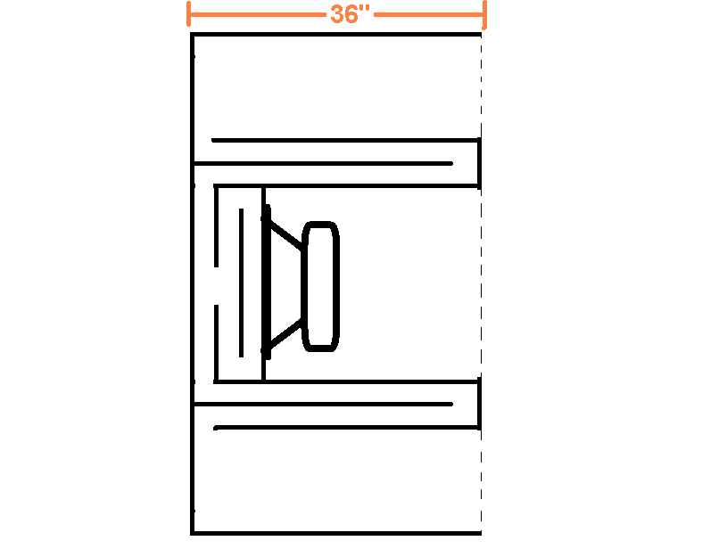
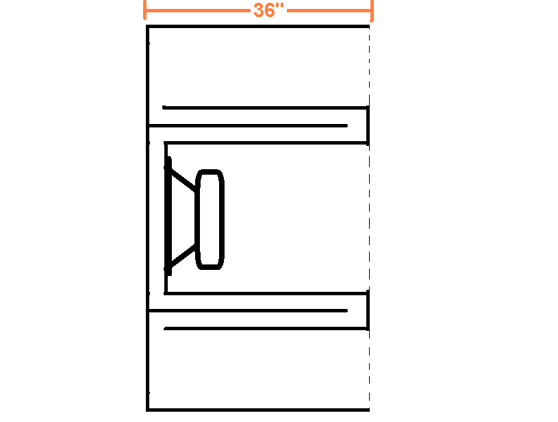
To "wave guide" waves, the guide must be acoustically large, the pictured "wave guide" could reduce turbulence, but little else, and the reduced area, dead space, would reduce SPL.Hi guys,
one question to this drawing:
Does the round front part have any acoustical effect like, say, forming some wave guide?
Cheers,
Art
@ Matthew Morgan J
Yeah i know about the "60hz with the upper peak at 130hz" stuff, Thanx
Sorry, but i'm still not being able to get you to understand what i meant !
Unless i'm mistaken, who me ? LOL, i'm sure you said that you planned for a higher fb in the front box. But it turned out to be lower than expected ? That's why i wondered if the DCR fb was affecting the front box tuning in some way. If it has, then that "might" account for the far left hand peak being lower in height & frequency than i would have expected to see, & the dip straight after that lower in frequency than i would have expected to see
Looking forward to your chic pics
Hi Brian,
Thanks, it's reassuring to learn that the predicted and measured impedance shifts are indeed similar.
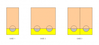
I think you are most likely right. The horn mouths would certainly need to be close together (similar to Case 3 in the attachment) for the "knee drop" to be seen in the measured results.
Now that sounds interesting....
Kind regards,
David
Here's a quick'n'dirty test I did with my POC3.1 TH this morning to demonstrate the impedance shift occurs as expected when the loading on the TH is changed.
Thanks, it's reassuring to learn that the predicted and measured impedance shifts are indeed similar.
I suspect that the different observations of what happens when multiple THs are used is dependent on *how* they're being used, because the mouth is so small compared to the cutoff frequency. Stacking two THs side by side so they're both on the ground and their mouths are touching along one side might be the closest one can get to moving from 2PI to 1PI. Putting one on top of the other however may not achieve that goal (one of them is loaded by the ground, the other is not).
I think you are most likely right. The horn mouths would certainly need to be close together (similar to Case 3 in the attachment) for the "knee drop" to be seen in the measured results.
(BTW, I might have an idea of how to emulate those box losses in Hornresp, but I need to test the approach a bit more...
Now that sounds interesting...
.Kind regards,
David
Attachments
So moving along, let's look at why we don't see much (if any) lowering of the knee when THs are stacked even though Hornresp does predict a bit.
Hi just a guy,
Many thanks for your comprehensive response. It would seem that in practice, the multiple horn mouths need to be positioned very close together for the knee to be lowered, even when the wavelengths are relatively long.
Kind regards,
David
Pondering the Mysteries
Zero D , we are going to get through this! hehehehe ....
....
The Fb wasn't the shocker so much ..
The thing that REALLY astounded us was the fact that the bass extension was reaching much lower than we had expected (underneath Fb)...
The Fb itself ended up being not too far off from what we were shooting for (just slightly higher than our target which must have had something to do with the DCR inspired section of the cabinet) ........
Nevertheless we experienced an intriguing amount of extension below Fb , but why? Did this also have something to do with the parasitic resonator section?? ...Perhaps.......
The roll-off was also expected to be very sharp, but it wasn't at all, instead it was rather shallow and musical , and yes it was all AS IF the Fb landed much lower , but it didn't, it was actually just a few hertz higher than our target... .
So there were definitely some mysterious surprises, but at least they were pleasant mysterious surprises of the highly fortunate type
The little squiggly anomaly that can be seen riding along the western slope of the lowest impedance peak (easier to see in the second screenshot that i posted in #186) indicates that something strange was going on, and considering the bonus bass extension that we were getting (along with well controlled cones) it makes me wonder if we had (by mistake) somehow generated a kind of lesser resonance down below, as in a weak or "mild" phantom resonance around the 56hz to 59hz range ....... It is just a guess of course, highly speculative stuff, but this is currently the best theory i could muster up to explain the weirdness that we observed ....
....
If i could have known about the amount of bonus extension that we were going to get below Fb i would have made those MTM-DC-MLQWP towers several inches shorter in order to tune them higher .. ... No need for so much overlap with the subwoofer in my friend's Home Theater system .....
If all goes well there should be more photos this fall and or winter .. *giggle*
@ Matthew Morgan J
Sorry, but i'm still not being able to get you to understand what i meant !
Unless i'm mistaken, who me ? LOL, i'm sure you said that you planned for a higher fb in the front box. But it turned out to be lower than expected ? That's why i wondered if the DCR fb was affecting the front box tuning in some way. If it has, then that "might" account for the far left hand peak being lower in height & frequency than i would have expected to see, & the dip straight after that lower in frequency than i would have expected to see
Zero D , we are going to get through this! hehehehe
.... The Fb wasn't the shocker so much ..
The thing that REALLY astounded us was the fact that the bass extension was reaching much lower than we had expected (underneath Fb)...
The Fb itself ended up being not too far off from what we were shooting for (just slightly higher than our target which must have had something to do with the DCR inspired section of the cabinet) ........
Nevertheless we experienced an intriguing amount of extension below Fb , but why? Did this also have something to do with the parasitic resonator section?? ...Perhaps.......
The roll-off was also expected to be very sharp, but it wasn't at all, instead it was rather shallow and musical , and yes it was all AS IF the Fb landed much lower , but it didn't, it was actually just a few hertz higher than our target... .
So there were definitely some mysterious surprises, but at least they were pleasant mysterious surprises of the highly fortunate type
The little squiggly anomaly that can be seen riding along the western slope of the lowest impedance peak (easier to see in the second screenshot that i posted in #186) indicates that something strange was going on, and considering the bonus bass extension that we were getting (along with well controlled cones) it makes me wonder if we had (by mistake) somehow generated a kind of lesser resonance down below, as in a weak or "mild" phantom resonance around the 56hz to 59hz range ....... It is just a guess of course, highly speculative stuff, but this is currently the best theory i could muster up to explain the weirdness that we observed
.... If i could have known about the amount of bonus extension that we were going to get below Fb i would have made those MTM-DC-MLQWP towers several inches shorter in order to tune them higher .. ... No need for so much overlap with the subwoofer in my friend's Home Theater system .....
Looking forward to your chic pics
If all goes well there should be more photos this fall and or winter ..
*giggle*
Last edited:
That bad boy looks awesome! Too bad for the wasted space tho'.
BP1fan,
It sure seems like it should have the potential to be a great solution for an SUV
Samuel's 8th order Super Planar will be used in a different setting (at home, and possibly PA from what i gather) ....
Be sure to post build pics and spl numbers!
The quarter wave pipes gets to long (to low resonant frequency) for the front resonators.
This is a way to shorten the quarter wave pipe without shortening the large front resonators.
We had to use the same solution in our ROAR series. I hate the dead unused space, but we could not find a better solution. We preferred to keep the easy build method with only straight sections and consistent 90 degree cuts.
Regards,
Johannes
A modification to the layout
GKH, Samuel, BP1Fan , and Johannes,
We are working on a modification to the B&C cabinet's layout in order to maximize the use of internal volume here (no more wasted space) .....
I am posting a few rough sketches (below) so you guys can see where we are going with this.....There are a few different ways that this design can be adapted for different path lengths while remaining efficient in it's usage of volume.... ....
and here again (below) when less path length is required .... The 8th order cabinet for the B&C will look more similar to this example....... The small CSA section of the main path on the 32hz tuned cabinet only needs to be in the 190cm to 200cm-ish range ...
Dustin is working on the 3D drawing ... He does such lovely work
GKH, Samuel, BP1Fan , and Johannes,
We are working on a modification to the B&C cabinet's layout in order to maximize the use of internal volume here (no more wasted space) .....
I am posting a few rough sketches (below) so you guys can see where we are going with this.....There are a few different ways that this design can be adapted for different path lengths while remaining efficient in it's usage of volume
.... ....
and here again (below) when less path length is required .... The 8th order cabinet for the B&C will look more similar to this example....... The small CSA section of the main path on the 32hz tuned cabinet only needs to be in the 190cm to 200cm-ish range ...
Dustin is working on the 3D drawing ... He does such lovely work
@ Matthew Morgan J
Re - fH & fL. Glad we understand each other now
Well, usually TL's are known for a less steeper roll off.
What do you think of the benefts, or not, of the symetrical 2 path box are, as apposed to just making the line one length ?
Nice images from your friend
Re - fH & fL. Glad we understand each other now
The roll-off was also expected to be very sharp, but it wasn't at all
Well, usually TL's are known for a less steeper roll off.
What do you think of the benefts, or not, of the symetrical 2 path box are, as apposed to just making the line one length ?
Nice images from your friend
- Home
- Loudspeakers
- Subwoofers
- Compound loading 6th order quarterwave "Super Planar" horns and pipes concepts/builds