CORRECTION
It is really too bad that DIYaudio won't let us go back and edit things after a half hour passes (or whatever the time limit is) ....
The following quote should read as follows :
CORRECTION :
I meant to say PSN1167 (not 1165 as said in the earlier post) .... The backs of the old Pyle horns that I have are labeled with "PSN1167" and are the 3.5" square model ....
The PSN1165 looks very similar but is larger at 4.35" (or so Pyle says)
Sorry about that guys , my mistake ..
It is really too bad that DIYaudio won't let us go back and edit things after a half hour passes (or whatever the time limit is) ....
The following quote should read as follows :
The very best cheap horn body i have found so far are the old style Pyle PSN1167 (with long silver phase plug), loaded with good elements (selected GRS and Goldwood) and these things are the most marvelous piezo combo i have ever come up with!I like them.
CORRECTION :
I meant to say PSN1167 (not 1165 as said in the earlier post) .... The backs of the old Pyle horns that I have are labeled with "PSN1167" and are the 3.5" square model ....
The PSN1165 looks very similar but is larger at 4.35" (or so Pyle says)
Sorry about that guys , my mistake ..
2x Delta-10A cabinet brainstorming
Might be less hassle
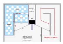
If you have the mic and software for measuring it would be really interesting to see how the waveguide recess depth affects the general response of the cabinet ....... Three measurements would be awesome, 1=All the way recessed , 2=Halfway recessed as shown in your sketch, and 3=all the way forward having the waveguide's mouth flush with the front of the cabinet. .... If it is not too much trouble .... You may find that the experiment is well worth the time , for the sake of optimization..
Keep in mind that Mr Vansickle chose to add a small flare to the HF waveguide's exit .... The flare may or may not be necessary for the purpose of controlled horizontal high frequency dispersion ... The HF waveguide seemed to be providing plenty of loading for the compression drivers within their working range (flare or not) ..
Gkh , yes , that is exactly the right idea For your 80hz-ish tuned cab you will want at least 15cm from the center of driver frame to the end of the "H" panel ...
It looks like you have the end of "H" panel trimmed about 7.6cm from the front of the cabinet (226mm - 150mm = 76mm) .... and as you said 226mm or 8.9 inches total from driver frame center to cabinet front ........ LOOKS GOOD TO ME!
I have to admit I will rather 3D print some wave guides than tinkering with a bunch of piezos :wink:
Might be less hassle
If you have the mic and software for measuring it would be really interesting to see how the waveguide recess depth affects the general response of the cabinet ....... Three measurements would be awesome, 1=All the way recessed , 2=Halfway recessed as shown in your sketch, and 3=all the way forward having the waveguide's mouth flush with the front of the cabinet. .... If it is not too much trouble .... You may find that the experiment is well worth the time , for the sake of optimization..
Keep in mind that Mr Vansickle chose to add a small flare to the HF waveguide's exit .... The flare may or may not be necessary for the purpose of controlled horizontal high frequency dispersion ... The HF waveguide seemed to be providing plenty of loading for the compression drivers within their working range (flare or not) ..
In my design, the 15cm don't go to the front of the enclosure, but to the front end of the panel forming the horn mouth.
Gkh , yes , that is exactly the right idea
For your 80hz-ish tuned cab you will want at least 15cm from the center of driver frame to the end of the "H" panel ... It looks like you have the end of "H" panel trimmed about 7.6cm from the front of the cabinet (226mm - 150mm = 76mm) .... and as you said 226mm or 8.9 inches total from driver frame center to cabinet front ........ LOOKS GOOD TO ME!
Last edited:

Hey MMJ,
there IS a small flare at the waveguide's exit - it just didn't move with the waveguide...
The distance is 100mm, actually, please see latest revision attached.
Oh , now i see it!
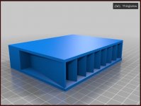
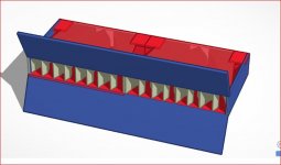
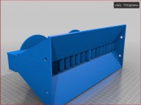
Some more tinkering with the waveguide. Now it's double plus a flare, angled 25° to match the toe-in of the bass speakers... One panel is transparent on purpose.
You can find it here.
To all the 3D pros: please bear with me - I'm a total noob at 3D design. Your comments and critics are highly welcome!
You can find it here.
To all the 3D pros: please bear with me - I'm a total noob at 3D design. Your comments and critics are highly welcome!
Attachments
Last edited:
Gkh, for a noob 3d design i would say you are 10 times better than me!
note for the link: i get the page is expired.
For 3D printing I would only design/print the inside part. Then do the rest with 12mm birch. 3d printing the whole thing is expensive. Or you could create a 3d printed template for router.
note for the link: i get the page is expired.
For 3D printing I would only design/print the inside part. Then do the rest with 12mm birch. 3d printing the whole thing is expensive. Or you could create a 3d printed template for router.

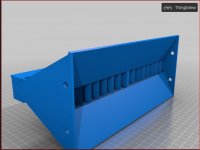
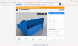
Nearly finished. Only thing missing are mounting flanges for the compression drivers. Progress can be see here (I hope this link works!)
Attachments


- Home
- Loudspeakers
- Subwoofers
- Compound loading 6th order quarterwave "Super Planar" horns and pipes concepts/builds