and some more
Well good morning then! Really! Hehe..... and you are very welcome, i am glad that you like these ideas.... .......
Be sure to have your coffee before firing up any power tools , don't want to lose any limbs!
GKH,
Before you get started on your serious drawings i wanted you to see a couple of variations on the cabinet ......
These were proposals .... One proposal was based upon the SUPER PLANAR Club Tops design which did work VERY well for us , and the other is a symmetrical design similar to the Line Array boxes that were built but with a simplified main path (less folds) and also features a deeper front chamber which is a good thing since as we found out it would have benefited us to extend the front chamber by a few inches on our real-world Line-Array cabinets (their front chamber depth was marginal, it was the minimal depth that still looked acceptable in the sim and it would have been better if depth was extended by 2" ) ....
The HF waveguide and front chamber are out of proportion on this first image , hence the honest disclaimer "ROUGH SKETCH" .... These were just some hastily cobbled concepts i was throwing at Vansickle back then, if he liked one in particular then I would get more serious about making a decent detailed sketch .....
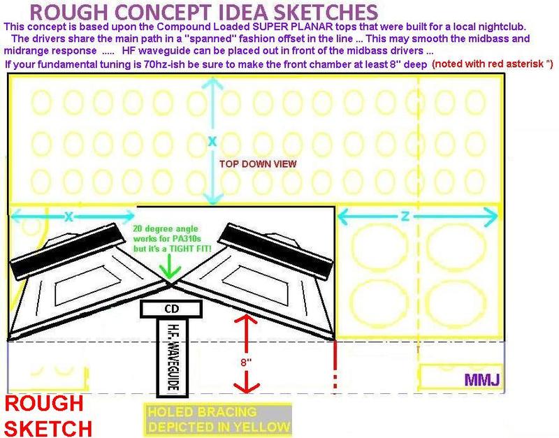
and here is a symmetrical path cabinet
and this is similar but front chamber depth is marginal , unless the tuning is higher (as it would be with your dual 10 version GKH)
Thanks again!
Will start drawing NOW
Didn't want to pull your leg - it's really 08:31 in the morning here
Regds
Gerald


Well good morning then! Really! Hehe..... and you are very welcome, i am glad that you like these ideas.... .......
Be sure to have your coffee before firing up any power tools , don't want to lose any limbs!
GKH,
Before you get started on your serious drawings i wanted you to see a couple of variations on the cabinet ......
These were proposals .... One proposal was based upon the SUPER PLANAR Club Tops design which did work VERY well for us
, and the other is a symmetrical design similar to the Line Array boxes that were built but with a simplified main path (less folds) and also features a deeper front chamber which is a good thing since as we found out it would have benefited us to extend the front chamber by a few inches on our real-world Line-Array cabinets (their front chamber depth was marginal, it was the minimal depth that still looked acceptable in the sim and it would have been better if depth was extended by 2" ) .... The HF waveguide and front chamber are out of proportion on this first image , hence the honest disclaimer "ROUGH SKETCH"
.... These were just some hastily cobbled concepts i was throwing at Vansickle back then, if he liked one in particular then I would get more serious about making a decent detailed sketch .....
and here is a symmetrical path cabinet
and this is similar but front chamber depth is marginal , unless the tuning is higher (as it would be with your dual 10 version GKH)
Last edited:
Impedance chat
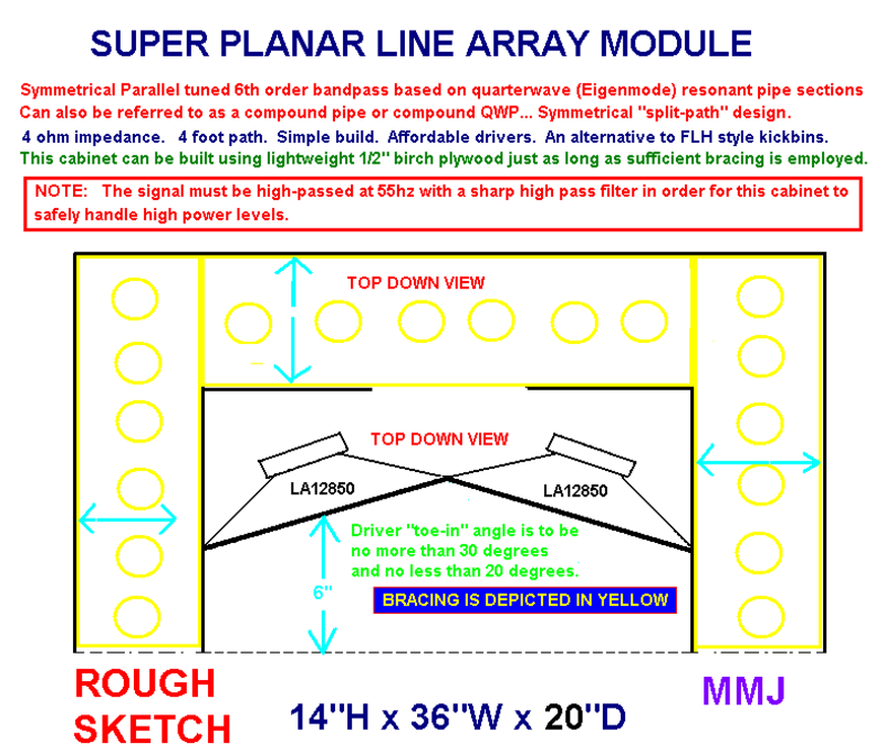
If a 4 ohm load (two Delta-10As in parallel) allows your amp to provide more headroom (as it is with most pro audio amps in stereo mode) then i would definitely stick with the Delta-10A drivers but i suppose it all depends on what you are trying to set up ........
If you plan on having multiples of these line-array modules on each side driven by the same amp then that could be different ......
BTW: what would you think about the Delta 10B 16Ohm?
If a 4 ohm load (two Delta-10As in parallel) allows your amp to provide more headroom (as it is with most pro audio amps in stereo mode) then i would definitely stick with the Delta-10A drivers
but i suppose it all depends on what you are trying to set up ........ If you plan on having multiples of these line-array modules on each side driven by the same amp then that could be different ......
No limbs lost, yet
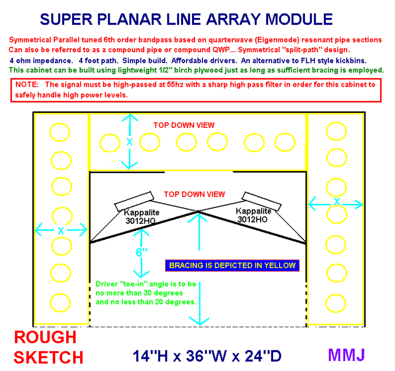
I really like the first version and have just finished my first - equally rough - sketch.
Mounting the baffles for the 10"s will be a bit tricky, but I think I can manage.
As the tops would be driven by plate amps, 4 Ohm shouldn't be a problem. The HF drivers should be X-overed passively, anyway (I can wind my own coils). I just came across the datasheet of the 10B and kinda liked it
BTW, do you have Adobe InDesign and/or Illustrator?
Attachments
Dual Delta-10A Super Planar Line-Array module chat
I took a look at it and you have the right idea Just be sure to make your front chamber deep enough .. If going with a constant CSA in the main (rear) paths then shoot for a path length of around 80cm to 90cm (per each main path) ..... If you plan to add some expansion in the path (as in the last segment and mouths having a larger CSA than the earlier part of the path) then you would want to make the path a bit longer , so say about 90cm to 100cm range for a reasonable amount of expansion which should be possible with that cabinet if making it 91.5cm wide (outer) ........... I can simulate two Delta-10As in such a cabinet and post the inputs and curve if you would like to see them ...
Driven by a strong plate amp that supports 4ohm loads along with a well designed passive high pass filter on the compression driver i think this could work very well .... You may find that you will have to adjust the values or configuration on your compression driver's high pass filter in order to compensate for the influence that the HF waveguide has on your response, especially when it is recessed deep into the cabinet the way it is (which also has an influence on response), a typical "textbook" filter probably won't provide the optimal HF response curve ....
I don't have those ones but i did learn to use Sketchup a few years ago, so i have that if i wanted to sketch something in 3D ... I haven't used it much since though.... I really just prefer to keep things as simple as fast as possible with the sketches ....
I really like the first version and have just finished my first - equally rough - sketch.
Mounting the baffles for the 10"s will be a bit tricky, but I think I can manage.
I took a look at it and you have the right idea
Just be sure to make your front chamber deep enough .. If going with a constant CSA in the main (rear) paths then shoot for a path length of around 80cm to 90cm (per each main path) ..... If you plan to add some expansion in the path (as in the last segment and mouths having a larger CSA than the earlier part of the path) then you would want to make the path a bit longer , so say about 90cm to 100cm range for a reasonable amount of expansion which should be possible with that cabinet if making it 91.5cm wide (outer) ........... I can simulate two Delta-10As in such a cabinet and post the inputs and curve if you would like to see them ...As the tops would be driven by plate amps, 4 Ohm shouldn't be a problem. The HF drivers should be X-overed passively, anyway (I can wind my own coils). I just came across the datasheet of the 10B and kinda liked it
Driven by a strong plate amp that supports 4ohm loads along with a well designed passive high pass filter on the compression driver i think this could work very well
.... You may find that you will have to adjust the values or configuration on your compression driver's high pass filter in order to compensate for the influence that the HF waveguide has on your response, especially when it is recessed deep into the cabinet the way it is (which also has an influence on response), a typical "textbook" filter probably won't provide the optimal HF response curve .... BTW, do you have Adobe InDesign and/or Illustrator?
I don't have those ones but i did learn to use Sketchup a few years ago, so i have that if i wanted to sketch something in 3D ... I haven't used it much since though.... I really just prefer to keep things as simple as fast as possible with the sketches ....
Last edited:
Good morning again
Thanks for giving me a head-up! Let me check my drawing and especially path lenghts, then I would greatly appreciate your sims.
The idea for HF filtering is first "building" an appropriate x-over with miniDSP, and later transferring in into hardware. Or, if that proves to be too complicated or costly, going full active. I intend to use two of the HF drivers, btw.
Sketchup I had, and used, but now it's a bit pricey. When time allows, I'm tinkering with AutoDesk Fusion 360 - but I'm still an absolute novice at it.
Edit:
Path length is nearly 110cm @ one side, CSA 367.2cm² on horn mouth; toe-in angle is 25°
Last edited:
Details
GOOD MORNING SIR! This is becoming our new routine i guess, haha!
No problem on the heads up
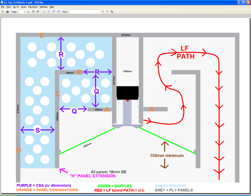
In order to put together the sim for you i will need a few more details ..... Referring to this color coded edit of your sketch (below) i need CSA values for "Q" and "R" , and you said "S" is 367.2cm² .......
That sounds like an excellent gameplan to me!
Which compression drivers did you have in mind? In your sketch it says "100mm" width available in the chamber where the compression drivers will tuck into .... The Faital Pro HF100 has a magnet diameter of 90mm so it should fit as long as you have the terminals oriented up and down ... ...
Ok , the toe-in angle is great , and the CSA on the last segment will work (doesn't look like we can get much more CSA there without making the cabinet wider or taller) ......... The only problem i am seeing here is the path length which will need to be shortened (probably by around 15cm) but i will know for sure how much it needs to be shortened when you provide those other CSA figures for me ...... I added some designations for the panels (in orange) for ease of discussion if we need to shift any panels or trim them in order to get the path length closer to our target....
Good morning again
Thanks for giving me a head-up! Let me check my drawing and especially path lengths, then I would greatly appreciate your sims.
GOOD MORNING SIR!
This is becoming our new routine i guess, haha! No problem on the heads up
In order to put together the sim for you i will need a few more details ..... Referring to this color coded edit of your sketch (below) i need CSA values for "Q" and "R" , and you said "S" is 367.2cm² .......
The idea for HF filtering is first "building" an appropriate x-over with miniDSP, and later transferring in into hardware. Or, if that proves to be too complicated or costly, going full active. I intend to use two of the HF drivers, btw.
That sounds like an excellent gameplan to me!
Which compression drivers did you have in mind? In your sketch it says "100mm" width available in the chamber where the compression drivers will tuck into .... The Faital Pro HF100 has a magnet diameter of 90mm so it should fit as long as you have the terminals oriented up and down ... ...
Edit:
Path length is nearly 110cm @ one side, CSA 367.2cm² on horn mouth; toe-in angle is 25°
Ok , the toe-in angle is great , and the CSA on the last segment will work (doesn't look like we can get much more CSA there without making the cabinet wider or taller) ......... The only problem i am seeing here is the path length which will need to be shortened (probably by around 15cm) but i will know for sure how much it needs to be shortened when you provide those other CSA figures for me ...... I added some designations for the panels (in orange) for ease of discussion if we need to shift any panels or trim them in order to get the path length closer to our target....
is there a hornresp Sim for this design?
I think MMJ is working on it.
Okay, some data and sim
Mr GKH , Hello
We want to make sure that your front chamber is deep enough to generate the resonance required to prevent the response hole that would otherwise occur somewhere in the in the 240-340hz range ...
So ok , lets try to optimize.
Referring to the PDF you attached at post #49 you have the immediate front chamber depth (the mass of air directly in front of the drivers) at 115mm ... It needs to be 150mm minimum ....
If we look at the sketch at post #47 we can use some of the designations there to discuss how we can get the 150mm that is needed ..... We can bring the "H" Panel Extension forward all the way to the front of the cabinet (this is how Mr Vansickle's Super Planar Line-Array cabs were set up), keep in mind that this can be easily trimmed after the build if you want to see the effects on response..... OR we could remove both of the "A" panels and then recess the driver's baffles further into the cabinet, this serves two purposes by shortening the LF path length and also gives us the front chamber depth that we need It would be great to get the LF path length down to the 100cm range if possible..
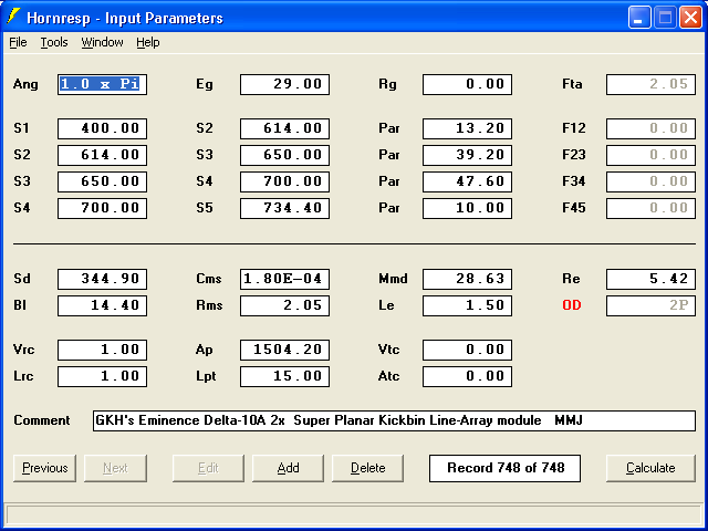
Alright , here are the inputs for the GKH Super Planar Line-Array module loaded with dual Eminence Delta10A drivers , modeled in quarterspace ("1 Pi" for indoors).... The expansion profile is approximated ........ This is with 110cm LF path length and a 15cm depth on the front chamber (which is the minimum,but a bit deeper is better) .............
Refer to the Hornresp inputs graphic in post #12 to show you how to set up the " Chamber Type ---> Rear Vented"
And here (below) is the frequency/amplitude response produced by Hornresp , it is heavily noted based upon our observations of the other Super Planar kickbin cabinets that were built ......
The output doesn't just fall to pieces above 350hz as Hornresp suggests, no, it will likely have a minor dip in that range but then immediately picks right back up and will carry out providing support right on into the upper-midrange ...
In that range where i added a thick red line the real world response won't be quite as smooth as what i had scribbled in but it is difficult to predict the small dip and bump anomalies that are sure to occur as we get higher in frequency, however you can expect to see the general contour of the Delta-10A's published graph reflected in the real world response with few extra wiggles
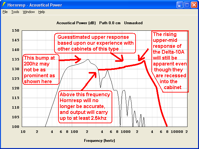
Honestly, the response will not be ruler flat but GKH i am sure you will find that the response is VERY useful, and the cabinet will deliver all the right stuff in all of the right places with plenty of warmth and punch, dynamics, great projection, and crisp clear vocals .......
If the squawking peak at 2.8khz is overbearing then there are ways to tone that down without losing too much of the precious 2khz output ..... Be sure to avoid excessive overlap between your Compression drivers and the Delta-10As , in fact you would be better off with a little dip in response at 3khz as opposed to an ugly sounding overlap in that range (our ears have a large peak in sensitivity centered right at 3khz) .... .
Your subs will need to support everything below 80hz ..
Mr GKH , Hello
We want to make sure that your front chamber is deep enough to generate the resonance required to prevent the response hole that would otherwise occur somewhere in the in the 240-340hz range ...
So ok , lets try to optimize.
Referring to the PDF you attached at post #49 you have the immediate front chamber depth (the mass of air directly in front of the drivers) at 115mm ... It needs to be 150mm minimum ....
If we look at the sketch at post #47 we can use some of the designations there to discuss how we can get the 150mm that is needed ..... We can bring the "H" Panel Extension forward all the way to the front of the cabinet (this is how Mr Vansickle's Super Planar Line-Array cabs were set up), keep in mind that this can be easily trimmed after the build if you want to see the effects on response..... OR we could remove both of the "A" panels and then recess the driver's baffles further into the cabinet, this serves two purposes by shortening the LF path length and also gives us the front chamber depth that we need
It would be great to get the LF path length down to the 100cm range if possible..Alright , here are the inputs for the GKH Super Planar Line-Array module loaded with dual Eminence Delta10A drivers , modeled in quarterspace ("1 Pi" for indoors).... The expansion profile is approximated ........ This is with 110cm LF path length and a 15cm depth on the front chamber (which is the minimum,but a bit deeper is better) .............
Refer to the Hornresp inputs graphic in post #12 to show you how to set up the " Chamber Type ---> Rear Vented"
And here (below) is the frequency/amplitude response produced by Hornresp , it is heavily noted based upon our observations of the other Super Planar kickbin cabinets that were built ......
The output doesn't just fall to pieces above 350hz as Hornresp suggests, no, it will likely have a minor dip in that range but then immediately picks right back up and will carry out providing support right on into the upper-midrange
... In that range where i added a thick red line the real world response won't be quite as smooth as what i had scribbled in but it is difficult to predict the small dip and bump anomalies that are sure to occur as we get higher in frequency, however you can expect to see the general contour of the Delta-10A's published graph reflected in the real world response with few extra wiggles
Honestly, the response will not be ruler flat but GKH i am sure you will find that the response is VERY useful, and the cabinet will deliver all the right stuff in all of the right places with plenty of warmth and punch, dynamics, great projection, and crisp clear vocals .......
If the squawking peak at 2.8khz is overbearing then there are ways to tone that down without losing too much of the precious 2khz output ..... Be sure to avoid excessive overlap between your Compression drivers and the Delta-10As , in fact you would be better off with a little dip in response at 3khz as opposed to an ugly sounding overlap in that range (our ears have a large peak in sensitivity centered right at 3khz) .... .
Your subs will need to support everything below 80hz ..
Hey Mr. MMJ,
thank you so much for your effort!
So, here's what I tried:
By removing panels "A", path lenght is rduced to approx. 1040mm. Panels "C" are now 436mm, thereby front chamber depth is exactly 150mm.
Didn't work out.
Next try - please find PDF attached. Path length is much nicer, overall dims remain the same.
Attachments
Looking good
GKH,
You are very welcome
Good work Sir, this is starting to come together well now
Hey Mr. MMJ,
thank you so much for your effort!
So, here's what I tried:
By removing panels "A", path lenght is rduced to approx. 1040mm. Panels "C" are now 436mm, thereby front chamber depth is exactly 150mm.
Didn't work out.
Next try - please find PDF attached. Path length is much nicer, overall dims remain the same.
GKH,
You are very welcome
Good work Sir, this is starting to come together well now
Last edited:

may I suggest to make more room around the CD driver. not all CD drivers have 100mm perfect cross diameter. this limit the design. also what about a few degree from front to back, between 4 an 6 deg. tapper.
Thanks for the suggestions!
The taper would have been my next question, makes beam steering much easier. Regarding space for the compression driver, I'd love to give it more room, but this depends on how wide the subs will be, as I want to have subs and tops exactly the same width.
Regds
Gerald
Regarding tapered enclosures: after giving it some thought, I fear that this reduction of CSA at near half of the horn's lenght would seriously affect it's behaviour.
Another weird idea that came up this hot and huid afternoon: a "Micro Array" consisting of two TC9FD18-08 per unit...
Another weird idea that came up this hot and huid afternoon: a "Micro Array" consisting of two TC9FD18-08 per unit...
- Home
- Loudspeakers
- Subwoofers
- Compound loading 6th order quarterwave "Super Planar" horns and pipes concepts/builds