some tracks sounded unconvinced and poorly.
Usually the driver needs a few hours of a few hundred watts before it sounds like it should.
some tracks has pressed guts out and the eggs shrank from fear
This would be a good description of my ROAR12, even though it still needs a few hours more workout.
Cheers,
Johannes
To be honest, if I was doing this design, I wouldn't use so many non-expanding sections - looking at it, it should only take a few minor tweaks to convert it to a single-expansion TH with a smooth expansion from S1 to S4, by mounting the internal panels at a slight angle to the path and adjusting their lengths accordingly. And then I'd be pretty sure that what I sim is what I get. In fact, looking even closer at it, it should be possible to convert it to a dual expansion TH with the driver at S3 instead of S4, but a bit more path length would be lost in the process.
Yes, and using an expanding flare instead of steps would give a much better frequency response too. The W shaped response could be kept if desired (even though it's a very undesirable response shape) and you get rid of the dreadful dip in response.
I can see why JAG has his hackles up so high about all this tbh. This feedback seems to correlate exactly with what you'd expect after the reasoned criticism about probable lumpy response, shown in sims, and also to a fair extent in the measured plots that you posted of the ROAR12 on hififorum.nu. But you see the good as the merits of the box design and the bad as the fault of the driver.Usually the driver needs a few hours of a few hundred watts before it sounds like it should.
This would be a good description of my ROAR12, even though it still needs a few hours more workout.
Cheers,
Johannes
We can assume the response gets a little more bumpy when measured from further than 1m, if only a little, but if what's been suggested about the worsening of response at high volumes is correct then you could easily be looking at -6dB troughs and +6dB peaks across a relatively narrow frequency band. Depending on music program being played, it's obvious that'll sound amazing or poor, but it really depends how critical you're being in your listening, and what environment you're listening in.
If I put a bass reflex sub indoors I can often expect to measure a similarly bumpy response, but subjectively I'll probably enjoy the music anyway, and unless I'm really listening critically I probably won't mind that uneven response - A lot of modern music program is carefully and deliberately mastered to sound good with those sort of level irregularities in the first place, because erratic room gain is a reality of most music playback.
But if that actually is how uneven the response at high volume is in halfspace (+/-6dB, somewhat erratically), what's going to happen if it's taken into a room that happens to excite the existing peaks and troughs by another 6-12dB? In some lucky cases it might even out, but in frequent other cases, it will be a total disaster.
So while in the majority of outdoor applications, or indoorrs at living room listening levels, the system probably holds up reasonably well (and I'm sure in any case it sounds great if you put the irregularities in response aside), the reliability for use indoors at high power levels will be significantly compromised. I would certainly have serious misgivings about these designs for professional indoor applications.
I'd be happy to be proved wrong about this as I have a lot of time for the THAM series, recommend them frequently, and other work produced by you guys in the past, and like many draw a lot of inspiration from your work, but I don't see the point in denying if the response is a bit peaky, and citing ancedotal stories about circumstance where it's worked amazingly well or sounded amazing, because I have no doubt that any of these designs are capable of working amazingly well, but they do at least appear to have potential irregularities that would compromise their flexibility and reliability to produce good sound at high sound pressure for professional applications in sub-optimal indoor environments.
For a lot of people who build powerful subs this is a - if not the primary consideration, and not one to be brushed aside.
Last edited:
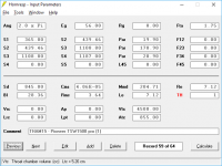
What were the DBX parametric EQ settings used to flatten the response?
F=47,5, G=-1, Q=0,56
F=90, G=-4,5, Q=3,41
F=126, G=1,5, Q=5,71
Based on the predicted diaphragm displacement i've set high pass at 28 Hz BW4 and low pass at 140 Hz BW2.
The response at the upper end of the passband drops like a rock. I've tried using EQ settings that resulted in a response like that between 100 Hz and 200 Hz for my subwoofers. I didn't like the results at all.
My mids are based on fast high-Qes full-range 12" and have enough kick at 100-150 Hz range, so i need exactly corresponding subs for open-air.
Usually the driver needs a few hours of a few hundred watts before it sounds like it should.
My drivers are sufficiently mashed at our laboratory, suppose of around a day at Xmax, but, yes, being drived a half of hour or so, bass changes to deeper and enveloping.
But if that actually is how uneven the response at high volume is in halfspace (+/-6dB, somewhat erratically), what's going to happen if it's taken into a room that happens to excite the existing peaks and troughs by another 6-12dB?
If it's taken indoors, than you probably living in a medium-sized castle with good gobelene damping and needs to carefully reproduce LFE of "The pirates of the Caribean".
There are a good russian obscene terms for doing this, they haven't straight equivalents, may be "beaten meat" would let you understand performing of 18" indoors... I believe that indoor you can use 10-12" in sealed box with good enough response.
I guess all the times I've spent indoors in front of a stack of 18" bass speakers must have been a figment of my imagination.
It's maybe not the most common application around these parts, granted, but there are corners of the Internet where people regularly come by looking for ideas for turning their 15 or 18" pro woofers into a system that could service small to medium sized events and concerts (<500 people usually). The idea of Cubo and THAM series are sometimes floated in those circumstances. If a plan is free and well documented it's always going to be considered. Obviously there's something of a long term feud going on with these guys and I'm not trying to be part of that but it seems there may be some grounding in reality for these concerns.
It's not at all clear that the THAM or ROAR series are even being designed with that sort of application in mind. while the Cubo by contrast has quite a lot of positive feedback around from people who've built large systems with it with good results. So anyway the ROAR series is interesting to me for that sort of thing, but not for home-theatre applications.
In English the word you're looking for is 'overkill', by the way. You can see how it has the same meaning to 'beaten meat' (ie, it's meat so it's already dead, if you kill it again it's overkill)
Last edited:
F=47,5, G=-1, Q=0,56
F=90, G=-4,5, Q=3,41
F=126, G=1,5, Q=5,71
This is great. Most tapped horns without excessive compression has a dip in the response in the very energetic midbass area. You have to eq down both the lower part of the passband and the midbass. 4,5 dB "to much" midbass is easy to eq to your liking and the very high efficiency in the midbass makes for an easy to power and often quite punchy bass.
Cheers,
Johannes
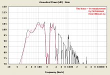
Yes, it will work.
Black line - your AE TD18H, gray - my RCF LF18X401.
View attachment 630984
But are you really want to feel an earthquake in your house?
Thank you. Спасибки!
My mids are based on fast high-Qes full-range 12" and have enough kick at 100-150 Hz range, so i need exactly corresponding subs for open-air.
Their rolloff at low frequencies isn't going to look anything like what the upper passband of that subwoofer now looks like, uinless you're using some pretty high-order HP filters on them. In my experience, high-order filters in the midbass region (which lead to such sharp cutoffs) don't sound "right", it might have to do with the high GD that could be introduced with the use of such filters.
What I usually end up doing with my current TH is use parametric EQ to get it flat to about 200 Hz, then roll it off around 100 Hz, 24dB/octave or less.
the S1-S2 distance (L12) that goes from the center of the driver to the edge, this is also a bit of a tricky area, and again I'm not sure which way is the correct one
Hi martinsson & Brian Steele,I don't think that S1-S2 length is correct in your sim - should be more like 0.1cm as per the alternate suggestion, as the center of the driver is right over the start of the path.
The assumption that S2 needs to be above the centre of the driver has no technical grounding. S2 only defines the throat area and its axial position, nothing more nothing less!!! Nowhere you will find that the throat necessarily needs to be in line with the piston.
Instead of using S1-S2 (L12) segment you can also use the Ap/Lpt function in Hornresp for this section. Some 'old school' designers prefer this method since they are used to treat the most narrowing point near the driver as the throat and any volume between cone and throat is considered as the throat chamber. The outcome is the same, so it is more a matter of personal choice.
Regards,
Djim
Thank you Djim for your help and your effort with making a better simulation model.
It is greatly appreciated!
I have been pondering your model and I will see if I can make some better measurements outside of my ROAR12 soon. The weather has been terroble the last few days.
Cheers,
Johannes
It is greatly appreciated!
I have been pondering your model and I will see if I can make some better measurements outside of my ROAR12 soon. The weather has been terroble the last few days.
Cheers,
Johannes
Hi Circlomanen,
No thanks needed, although it is always appreciated.. Imo you guys made a great DIY design by keeping cuts 90 degrees and using the structural benefits of the symmetric split-path to increase its stiffness. That there are pay-offs counts for every design...
Btw sorry for my earlier "zero" comment since I didn’t see the expansion was starting in the last fold and not after.
I wouldn't worry about your indoor measurements too much....
Perhaps looking for a driver that does like 1/4WL tapped 'thingies' would help ;-)
Regards,
Djim
No thanks needed, although it is always appreciated.. Imo you guys made a great DIY design by keeping cuts 90 degrees and using the structural benefits of the symmetric split-path to increase its stiffness. That there are pay-offs counts for every design...
Btw sorry for my earlier "zero" comment since I didn’t see the expansion was starting in the last fold and not after.
I wouldn't worry about your indoor measurements too much....
Perhaps looking for a driver that does like 1/4WL tapped 'thingies' would help ;-)
An externally hosted image should be here but it was not working when we last tested it.
Regards,
Djim
Hi martinsson & Brian Steele,
The assumption that S2 needs to be above the centre of the driver has no technical grounding. S2 only defines the throat area and its axial position, nothing more nothing less!!! Nowhere you will find that the throat necessarily needs to be in line with the piston.
Hmm...
The way I know how to use it, S2 in a TH defines where the center of the driver's output at that part of the horn , and S1 and L12 define the CSA of the horn at its start and the offset of the driver's center from the start of the horn. Ap1 and Lp can be used to include the baffle cutout in the sim, and Vtc and Atc used to define the volume of air between the driver's cone and the cutout, basically the "throat" of the TH.
In fact, if you put your mouse pointer over Vtc in HornResp, it shows "Vtc - Throat Chamber Volume". As David McBean actually wrote the software we're using to sim these things, I think I'll go with his approach to simming them
")
Attachments
Please rememeber that my B&C 12PS100 is almost brand new and needs a few hours of workout before the suspensions loosen. My measurement clearly show a too high fs and too stiff suspensions, so they should not be taken as a validation of the ROAR12. Even so there is a clear correlation beteende your simulation model and the measurement.
Cheers,
Johannes
Cheers,
Johannes
Last edited:
Please rememeber that my B&C 12PS100 is almost brand new and needs a few hours of workout before the suspensions loosen. My measurement clearly show a too high fs and too stiff suspensions, so they should not be taken as a validation of the ROAR12.
Cheers,
Johannes
How did you measure it? If you used a low signal level (like what DATS v2 uses), this might be "par for the course", as my measurements of a B&C 18" TBX driver showed the same behavior. It performed as expected in the TH I built for it though.
Hi all,
Seems like my earlier link doesn't work.
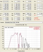
Meanwhile I finished the model for the Roar12
@Brian, perhaps you should show us your sim.
Regards,
Djim
I'll have a look at it this week. I've been tied up trying to finish a disaster of a project over the last few days of my vacation, and it's back to work tomorrow, when the very first thing I might have to do in the morning is let one of my team members know that his job was made redundant. I'm not looking forward to it
.Hi Brian,
One of those things you don't miss after you're retired. Wishing you good luck is perhaps inappropriate but as long the reason is 'clean' than make sure it is just one of those things.
Anyway, looking forward to your findings.
@ Circlomanen, Johannes I modelled the wrong driver as I thought you measured the Beyma. It is closer now, although the differences are small.
Regards,
Djim
Attachments
The assumption that S2 needs to be above the centre of the driver has no technical grounding. S2 only defines the throat area and its axial position, nothing more nothing less!!! Nowhere you will find that the throat necessarily needs to be in line with the piston.
WUT?
The first two sentences in this paragraph directly contradict each other. S2 defines the cross sectional area in all designs and it indicates the driver position along the axial length of the horn flare in all TH (and OD) designs. Therefore the second sentence is correct and the first sentence is not. But even though the second sentence is correct that is not how you simulated it.
Brian is right, of course, the only thing I would change in his statement is that L12 should be 0.01 cm instead of 0.1 cm.
What difference does that make? S1 is assumed to be a solid boundary and there will always be a deep notch associated with the boundary reflection at a frequency related to the S1 - S2 length (L12). In this design it doesn't appear as a deep notch due to the variety of resonances in the 400 hz region (where the notch appears) but you do still clearly see a notch in that range even in your sim.
Not that it matters though - the more than 1/2 octave wide 22 db deep black hole at ~140 hz means nothing above 140 hz really matters and that it will be impossible to get a good crossover transition to the mains. Just look at the damn thing, it's almost a vertical line dropping down at 140 hz, likely much steeper than 96 db/oct drop. Even if you had hardware that could cross the mains at that slope it would sound terrible, as Brian said.
Instead of using S1-S2 (L12) segment you can also use the Ap/Lpt function in Hornresp for this section. Some 'old school' designers prefer this method ...
I assume you mean vtc/atc here, not ap/lpt.
Using vtc/atc to define the S1 - S2 area is simply the wrong way to do it. There will be a deep notch related to the L12 distance and that notch won't show up in the sim if you treat the S1 - S2 volume as a throat chamber.
You can clearly see the error if you look at sims done this way. Danley simulated the Labhorn this way and the sims don't match the measurements at all. You can make the sims match the measurements though, all you have to do is sim it accurately.
Other than those two points though, you did a good job on the sim. L12 definitely should be 0.01 cm, not 20 cm, but in this case it hardly matters as the notch is way too high in frequency to matter in this design due to the massive 1/2 octave wide 22 db hole that kills this thing as a viable design for anyone that knows anything about system integration.
How did you measure it?
With REW and an UMIK. My ROAR12 was powered by a 3 watt single stage class A amplifier, using about 3 volts output level.
I will use my QSC RMX1450 when I measure it outside.
- Home
- Loudspeakers
- Subwoofers
- ROAR18