What do you mean by 'measurements', do you mean in a sim or on the actual builded one?
Of the actual built one. Yes
i'd like to see some atra or rew measurments,on this roar 12,15 and 18.
can anyone point me a link?
Very...!
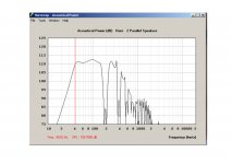
quick post, not sure if it's been up here before, here is a indoors REW measurement of a ROAR12 equipped with 12PS100, powered by a Digam Powersoft K10 and processed via a DBX Driverack 260.
Martinsson's Blog -ROAR12 testing
As for directivity I have no measurements, only subjective impressions compared to 18"BR, the impression received by those attending the test linked to above was that the ROAR12 was clearly noticeably more directional in comparison to the BR, some of the persons walked around the ROAR12 and smiled, later commenting on the subjectively experienced directivity, that all, only subjective impressions.
Last edited:
tnx for that martinson.
you noted that the actual measurement revealed lower tuning than the sim.
in the sim there is no troat chamber to compensate driver volume and baffle cutout.
thats maybe 1~2hz dif.
ad that to the xtra volume in the folds ,it seems about right.
grts erik
you noted that the actual measurement revealed lower tuning than the sim.
in the sim there is no troat chamber to compensate driver volume and baffle cutout.
thats maybe 1~2hz dif.
ad that to the xtra volume in the folds ,it seems about right.
grts erik
quick post
~1kW without any HP filtering
Very suspicious...
While there are a very helpful driver displacement at freq's lower than tuning frequency, there are absolutely no doubt they must override 12PS100's Xmech at 1kWt.
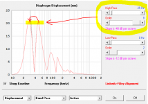
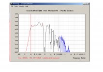
For ROAR18 with Driverack family or DCX2496 i'm using strong 48 dB/oct LR8 filter at around 25 Hz. Attached pic provide easy and understandable goal for HPF tuning. Use audibly-preferred filter, lift HP freq for same level of displacement upper and lower than tuning frequency. This will provide you with good level of LF-extension and simultaneously good heat dissipation with safe displacement run.
Low-freq displacement rising very needed for heat dissipation, driver suspension acts as a pump for moving air, so coil effectively vented. Keep in mind useful subharmonic synth, provided by Driverack's, this also useful for some kind of program material with lack of lower extension.
May i suppose KDSP module inside K10's or some kind of HPF inside soundinterface/soundcard?
Attachments
Last edited:
CBe18
Hi Brian, Could you please share hornresp input data for the simulation and spreadsheet.
It just occurred to me that the layout of the ROAR is very close to the layout of the Cyclops. The only thing significantly different is that the Cyclops has an extra fold at the back, which results in shorter box for the same path length. The simulated response curves are pretty close too (see attached). As I've got a spreadsheet that can (theoretically) optimize a Cyclops fold, it shouldn't take much to change it to use a ROAR fold as well. If I have some time this weekend, I'll have a look at it.
Hi Brian, Could you please share hornresp input data for the simulation and spreadsheet.
References and comparisons between the ROAR and the cyclops has been made before, and while it is true that if regarding it purely from a "where are the bends" point of view it is similar I grant you, but outside of this there are differences, I would go further and say clear differences, between the two.
The most significant of which would be the quarter wave resonator, compared to the ROAR the cyclops do not have the last long constant area segment (post summation quarter wave resonator) the other one would be that the cyclops is a expanding (incrementally stepped or otherwise) design all the way trough.
Just to be clear - the cyclops is a very good design with many happy builders/users in it's catalog, this to me is a prime indicator of a great design, and from a spreadsheet folding scheme point of view the cyclops might be the best candidate to build upon to save time, this I can see to some extent (not having done it myself).
I write this for the sake of clarification only, there are many people reading these threads with various levels of understanding and I do not want to run the risk of taking anything away from the cyclops design.
Hello Martinsson.
Thank you for ROAR 10 model. I have build several of your projects like Th6, Tham10 and TPAM10HTL version with 10NW64 and all of them work just fine!
My question is: If we change the last section of the ROAR10 to "horn like" will it make the response wider in 200hz+?
Thank you.
Thank you for ROAR 10 model. I have build several of your projects like Th6, Tham10 and TPAM10HTL version with 10NW64 and all of them work just fine!
My question is: If we change the last section of the ROAR10 to "horn like" will it make the response wider in 200hz+?
Thank you.
Attachments
Last edited:
will it make the response wider in 200hz+
No. Main limit is resonator length and volume. Your suggestion changes params lower than 10%, so mostly equal to driver suspension stiffness training/preheating or daily air temperature and humidity changes.
No. Main limit is resonator length and volume. Your suggestion changes params lower than 10%, so mostly equal to driver suspension stiffness training/preheating or daily air temperature and humidity changes.
Thank you,
Спасибки. Опять.
ROAR15_mod
Hi all,
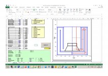
I tried to mod the ROAR 15 using Brian Steeles' spreadsheet, it optimizes the box resulting in a slightly smaller box. Please check and confirm if I am lost or seeing the light
I plan to build a "2x15 ROAR" sized: 730x 1000 of the optimized version. Must I put a pannel to separate the woofers or not? What are the effects or both?
Hi all,
I tried to mod the ROAR 15 using Brian Steeles' spreadsheet, it optimizes the box resulting in a slightly smaller box. Please check and confirm if I am lost or seeing the light
I plan to build a "2x15 ROAR" sized: 730x 1000 of the optimized version. Must I put a pannel to separate the woofers or not? What are the effects or both?
Attachments
Last edited:
Make sure that you're using the spreadsheet version from this post:
http://www.diyaudio.com/forums/subwoofers/309303-roar18-21.html#post5306758
That version contains a few improvements.
Also, make sure that the panel thickness setting is correct. 0.75" is more like 1.9cm, not 1.8 cm.
http://www.diyaudio.com/forums/subwoofers/309303-roar18-21.html#post5306758
That version contains a few improvements.
Also, make sure that the panel thickness setting is correct. 0.75" is more like 1.9cm, not 1.8 cm.
Make sure that you're using the spreadsheet version from this post:
http://www.diyaudio.com/forums/subwoofers/309303-roar18-21.html#post5306758
That version contains a few improvements.
Also, make sure that the panel thickness setting is correct. 0.75" is more like 1.9cm, not 1.8 cm.
Its the one you posted, the panel thickness is correct. Is the exit not too narrow? The original ROAR15 and the Cyclops have a larger exit.
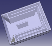
I'd like to share a couple of notes on how we judged the influence of the front resonator, as it is of great importance for the designs performance.
The front resonator area will influence the overall passband sensitivity, and the length of the front resonator influences the center frequency boost given by the same.
The ROAR designs strives to maximize the resonator length in relation to total enclosure depth trough a split path, effectively halving the first segment dimension in the depth direction, the split path also serves to maximize enclosure stability and simplify bracing by minimizing single sheet exterior surfaces around the front resonator, reducing it from potentially three sides to two, these are then stiffened up by a single brace.
When comparing the ROAR designs to the majority of tapped horns designs it is easy to see that the distance from the driver (summation point) to the aperture is far longer, this would be the front resonator, a simple approach to lift the passband at it's otherwise lowest point in the case of a constant area based system, all while making the design very easy to build.
Last edited:
Its the one you posted, the panel thickness is correct. Is the exit not too narrow? The original ROAR15 and the Cyclops have a larger exit.
That image capture looks like it is from the earlier version of the spreadsheet. The expansion near the driver is treated differently in the later version. Check the version number to see if is is 0.3. If it's not, then it's not the latest version.
If the exit is too narrow, then you need to increase the width or height of the enclosure.
The spreadsheet provides an optimized design, i.e. all volume contained within the external dimensions that you provide for the enclosure are used by the horn. The ROAR 18 enclosure, as provided on Martinsson's website, is not optimized. Have a look at the front.
This is very much intended, the resoator center frequency, i.e it's length, needs to be balanced towards to length of the first segment, and seeing that the resonator provides the highest sensitivity boost when combining these two we altered the length of the first segment instead, making it shorter in relation to the front resonator, this means raising the lower knee both in level and frequency resulting in a more even passband according to the simulation model we used.The ROAR 18 enclosure, as provided on Martinsson's website, is not optimized. Have a look at the front.
But you are correct, if the optimization is to consider internal/external volume usage only then all ROAR designs except the ROAR15 is not optimized, this is how we choose to balance the resulting passband, but you could get a lower knee both in level and frequency by extending the first segmet all the way to boundaries of the enclosure, as per the optimization in the spreadsheet, it' a matter of taste i guess.
- Home
- Loudspeakers
- Subwoofers
- ROAR18