If they will be equal to the THAM designs regarding volumetric efficiency given similar tuning and driver size remains to be seen, but is looks very promising, they will no doubt be bigger but also significantly more efficient, what is certain though is that they will be a lot easier to build than the THAM designs (which has been well received in this regard).
Hi martina,
I'll attach the dxf file w/ the extension changed to .txt, just change it back to .dxf, and it should work. I used 3/4"nom. 23/32" plywood in the drawing.
Regards,
If they will be equal to the THAM designs regarding volumetric efficiency given similar tuning and driver size remains to be seen, but is looks very promising, they will no doubt be bigger but also significantly more efficient, what is certain though is that they will be a lot easier to build than the THAM designs (which has been well received in this regard).
Have you ever considered a tham15 that simply stretches the depth of the cabinet, to get a slightly longer path length, without any extra folds?
Have you ever considered a tham15 that simply stretches the depth of the cabinet, to get a slightly longer path length, without any extra folds?
That was my idea
")
Hi turbodawg,
Post #22: "Have you ever considered a tham15 that simply stretches the depth of the cabinet, to get a slightly longer path length..."
Martina's box dimensions add about 3.9" per horizontal horn path segment in my drawing (Post #10). I still like it better w/ the added bottom segment, but it depends on how low you want to go. My original drawing used dimensions to provide for better wood use w/ 4'x8' sheets...
I think the original THAM15 was optimized for minimum cabinet size, but martinsson can elaborate on that.
Regards,
Hi turbodawg,
Post #22: "Have you ever considered a tham15 that simply stretches the depth of the cabinet, to get a slightly longer path length..."
Martina's box dimensions add about 3.9" per horizontal horn path segment in my drawing (Post #10). I still like it better w/ the added bottom segment, but it depends on how low you want to go. My original drawing used dimensions to provide for better wood use w/ 4'x8' sheets...
I think the original THAM15 was optimized for minimum cabinet size, but martinsson can elaborate on that.
Regards,
Thanks! I saw the drawing from post #10 and it looked really great, but considerably more complex to build than a normal tham15. It seemed like the normal tham15 could be extended back, and still keep the simple design? Like the proportions of the tham10 here:

Last edited:
As far as I understand the principle requires the driver to be located at the far (inner most) end of the resonator, along with the tapping function, the THAM designs do not rely on any form of quarter wave resonator loading after the tapping function.
Making a THAM design folding "deeper" and moving driver as far in as possible would add a quarter wave resonator loading function to the tapped sum, this would however mean that you end up with an excessive L12 length, or a larger unused (enclosed) volume in the folding (similar to the one shown in the bottom right corner in the development THAM10 release above).
Am I understanding you guys right? or did I miss something in your question?
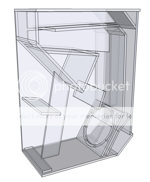
This is a work in progress, this far the folding I found that makes the best use of the cabinet dimensions, specially the depth which is critical since it determines the QWR function tuning, can be seen below, this also allows for the minimum amount of outer single wall surfaces (two) in need of coupled bracing :

This is a work in progress, so don't take the above picture to seriously.
Making a THAM design folding "deeper" and moving driver as far in as possible would add a quarter wave resonator loading function to the tapped sum, this would however mean that you end up with an excessive L12 length, or a larger unused (enclosed) volume in the folding (similar to the one shown in the bottom right corner in the development THAM10 release above).
Am I understanding you guys right? or did I miss something in your question?
This is a work in progress, this far the folding I found that makes the best use of the cabinet dimensions, specially the depth which is critical since it determines the QWR function tuning, can be seen below, this also allows for the minimum amount of outer single wall surfaces (two) in need of coupled bracing :
This is a work in progress, so don't take the above picture to seriously.
Last edited:
The last TH I built was also a 15" with a big deep mouth, for use in big stacks.
TH18 for scale:

TH18 for scale:
An externally hosted image should be here but it was not working when we last tested it.
The THAM15 (designed in 2009) was my first attempt at designing a tapped horn, and I spent a lot of time together with Johannes Rodin, co-designer of the entire THAM series, along with support from various forums trying to get a fold that provided as much as possible in terms volumetric efficiency (dB/W/m/m3) in a real world usable range (~40Hz and up).I think the original THAM15 was optimized for minimum cabinet size, but Martinsson can elaborate on that.
Keep in mind that the THAM15 design roughly eight years old now, a lot has happened with regards to our understanding of the tapped horn design principle, the excellent software Hornresp provided by David McBean and driver development since then.
Given that a lot of absolutely excellent tapped horn and other designs has sprung from various open collaborative forum efforts over those eight years I'm very happy to say the popularity of the THAM designs has stayed fairly high and they are still very popular.
Nice one EPA, it is indeed very similar with regards to the folding, but there is one significant difference, I may be wrong (standard state of mind) but the response graph does not indicate a QWR function (a middle peak), this may be due to a non constant area folding and lack of depth in the aperture chamber (QWR length).
I guess this (QWR loading) was not your intention with this design so feel free to disregard that nice work, did it make into a build?
I guess this (QWR loading) was not your intention with this design so feel free to disregard that
nice work, did it make into a build?

Here is my TPQWR build from about a year ago.
I use two Beyma 12P80Nd.
https://youtu.be/6bkF0J6wOKU
I rattle a cardboard box with a 10 watt "plateamp" - a Logitech computer loudspeaker.
The microphone in my smartphone clips and distorts badly.
Cheers,
Johannes
Last edited:
Making a THAM design folding "deeper" and moving driver as far in as possible would add a quarter wave resonator loading function to the tapped sum, this would however mean that you end up with an excessive L12 length, or a larger unused (enclosed) volume in the folding (similar to the one shown in the bottom right corner in the development THAM10 release above).
Am I understanding you guys right? or did I miss something in your question?
Ah thanks. I actually didn't mean moving the driver in. I meant leaving the driver at the front where L12 can be very short and making the cabinet slightly deeper. Since there are 3 horizontal path sections, a 4" increase in cabinet depth would give about a foot more path length?
it was just another fold atempt of a th .Nice one EPA, it is indeed very similar with regards to the folding, but there is one significant difference, I may be wrong (standard state of mind) but the response graph does not indicate a QWR function (a middle peak), this may be due to a non constant area folding and lack of depth in the aperture chamber (QWR length).
I guess this (QWR loading) was not your intention with this design so feel free to disregard that
not 100% sure the sim is the right one.
just under 450 ltrs and easy to adapt to varius drivers ,with minor changes.
it was never bild btw.
@Turbodawg
I really like the idea of making the tham15 deeper. I build a few protos, but did not want to stack them more then 2 high because I was worried the stack could tip over. Making the tham about 20cm deeper would make it more square and also more robust in stacking and possible a bit lower in hz.
@Neo-dan that is an insane looking TH. I first thought it was a FLH design but then I looked closer and had a wtf moment. Do you have any sims on it? I would love to proto-build one if I may.
But first I need to build the TH218SC prototype. I wanted to do this in the christmas holiday but then my friends decided to give me a new saw-table as present. That was a big and heavy surprise. Which I am putting together at the moment. so a little delay on that build.
I like doing sims any day but I have more enjoyment in building prototypes and testing for hard evidence
Due to the way the THAM folding scales making it deeper alone will not work without messing up the expansion, but that might be self explanatory, the only way I know to keep the height intact and increase the depth with maintained expansion throughout the path is to reduce the S1 & S2 and /or the S3 & S4 areas.
If you want to make a lower tuned THAM folded TH here are a few things I kept in mind when designing the original :
Decreasing the S1 & S2 will increase the stress on the driver at higher power levels which might introduce distortion.
Decreasing the S3 & S4 will leave you with less surface coupling to the air outside the box which might negatively impact the overall efficiency.
Increasing the path length alone to tune it lower will most likely reduce the efficiency, if you want to keep the efficiency and tune it lower you need to scale the cross section surfaces along with the path lengths meaning scaled up box dimensions overall.
I do not mean to discourage you from trying this, I only wanted to make sure you know what I see as the potential downsides that might arise in this so you can balance it in a better way from the start if you want to pursuit a lower tuning.
Post #10/13/24...
Hi Y'all,
So much interesting stuff.
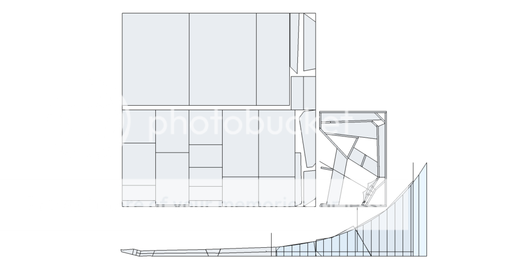
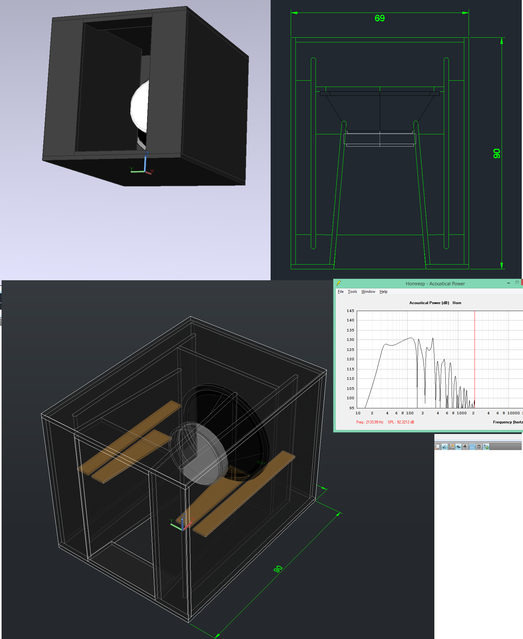
I worked up a THAM15_Forsman TH using martina's internal dimensions from Post #13. As you can see in the development the added depth does make a big difference, as we are extending five segments of the horn path. There also will be a little fudging.
The response looks nice, naturally, there will be a loss of SPL along w/ the low frequency extension. Your choice.
I made a few notes as to cone correction, but I don't have a known accurate drawing of the B&C 15NW100, i.e. cone size and depth... Just some thoughts. It becomes obvious that for a driver with a deep enough cone there is enough area in the cone for S2...
Don't have time to do any more, back to trying to fix the plumbing under the concrete slab. (Don't by an old house w/ old cast iron plumbing.)
Regards,
Hi Y'all,
So much interesting stuff.
I worked up a THAM15_Forsman TH using martina's internal dimensions from Post #13. As you can see in the development the added depth does make a big difference, as we are extending five segments of the horn path. There also will be a little fudging.
The response looks nice, naturally, there will be a loss of SPL along w/ the low frequency extension. Your choice.
I made a few notes as to cone correction, but I don't have a known accurate drawing of the B&C 15NW100, i.e. cone size and depth... Just some thoughts. It becomes obvious that for a driver with a deep enough cone there is enough area in the cone for S2...
Don't have time to do any more, back to trying to fix the plumbing under the concrete slab. (Don't by an old house w/ old cast iron plumbing.)
Regards,
Attachments
- Status
- This old topic is closed. If you want to reopen this topic, contact a moderator using the "Report Post" button.
- Home
- Loudspeakers
- Subwoofers
- Tapped Horn for B&C 15NW100