Hi 4392Viper,
Post #18: "...correct me if I went wrong..."
Somehow diyaudio "ate" my last post, anyway, if you have another chance at messing around with passive radiator alignments, please, start with a driver with known real T/S parameters.
I'm almost certain that your conclusions are very heavily influenced by the use of a peculiar 6.5" driver with a strange Vas.
You will find that there is a relationship between the mass of a passive radiator, and the mass of a tuning duct of equal cross-section. You will also find that a passive radiator system needs a PR that has an Fp well below the system resonance, and that very often the PR needs to be loaded down with a substantial amount of weight.
Here is an excellent thread on PE Tech Talk that has a lot of information about passive radiators. Look particularly for the posts by Jeff B. (that's Jeff Bagby, the loudspeaker designer, who wrote a very nice Excel spreadsheet for loudspeaker design with particular emphasis on passive radiators):
Small PR in bookshelf speakers - Techtalk Speaker Building, Audio, Video Discussion Forum
Also, look at this:
AE Speakers --- Superb Quality, Unforgettable Performance, Definitely.
Don't give up on PRs because you got stuck with a questionable driver and an even more questionable PR. It's a great way to get a very big duct into a much smaller volume...
Regards,
Thanks tb46,
I highly doubt my testing equipment to be faulty. I even calibrated my multi-meter and amplifier.
Could you please kindly do me a favor and test this T/S calculator with a driver with known parameters as I don't have one around.
T-S Parameter Calculator
Or can you please send me the trusted equations to the calculations?
This page is supposed to be helpful,too.
Measuring Loudspeaker Driver Parameters
but I see in in the equations some parameters that are not introduced in the article, such as Is, Im.
I think I can work more on the alignment, at least my current one suffers from port chuffing.
And this 12" cone is so stiff I can't make anything useful out of it, except for a comfortable seat . I have to go buy another PR and see what I can do.
Regards, Ali
... a peculiar 6.5" driver with a strange Vas.
I highly doubt my testing equipment to be faulty. I even calibrated my multi-meter and amplifier.
Could you please kindly do me a favor and test this T/S calculator with a driver with known parameters as I don't have one around.
T-S Parameter Calculator
Or can you please send me the trusted equations to the calculations?
This page is supposed to be helpful,too.
Measuring Loudspeaker Driver Parameters
but I see in in the equations some parameters that are not introduced in the article, such as Is, Im.
I think I can work more on the alignment, at least my current one suffers from port chuffing.
And this 12" cone is so stiff I can't make anything useful out of it, except for a comfortable seat
. I have to go buy another PR and see what I can do.Regards, Ali
Last edited:
The testing method of that calculator works. But just kinda - depending on the circumstances. It's usually fine but there are a lot of possible error sources in that kind of measurement, especally if the drivers are extreme.
At first, the calculation for the Sd ist just a very crude method, that works for most bigger chassis i.e. 8" and up. With smaller and non-standard drivers, especally with huge surrounds you get more of an estimation. I'd suggest you measure it itself (membrane + 1/2 surround).
The second issue is, unless you are measuring the voltage with an oscilloscope or a very good analogue voltmeter, in most cases it doesn't measure as low as 1 Hz properly and often not linear at all. Especally digital voltmeter have big issues there and the usual additional +/- 1 digit tolerance (on top of the x% tolerance) makes a huge difference.
It's advised not to use that method to get the Re if you don't have the gear, use a good multimeter for the Re, even if mixing the measuring methods can introduce other errors. But you can compare/verify the measurements if you measure the 10 ohm resistor and after that the resistance of your multimeter (put the prod tips on each other) and check with the voltage measurement result.
3rds, the heavier the Mms of the speaker, the more mass you have to add to get reasonable differences. The other way around 30g are way too much for small drivers and it even moves the coil WAY out of the zero excursion position. For other drivers with high Mms 30g is too low. If you divert from the added mass, ofcourse you have to adjust the value on the calculator.
Besides that, loose pennies or other stuff of that size tends to move, even if you can't see it, more critical at higher fs or excursion. Kneading dough i.e. or fixing the weight on the membrane helps there a lot. On a paper membrane you can add the weight at the back of the membrane (as close as possible to the coil and it has to be symmetrical).
4th and most important for measuring such extreme drivers, the signal is way too weak for such extreme drivers because of the huge losses in the system, the speakers simply doesn't work properly at such levels. If you didn't know, the parameters drift with the power and excursion. You have to measure these subwooferchassis with much more power (i.e. ~1W at the driver for bigger high loss subwoofers). Most frequency generators can't deliver that power and you need an amplifier for it - but there's the next problem, with most amplifiers you can't get as low as 1 Hz. -35dB @1Hz is quite common, often even worse. If you try to compensate that with more gain, you get a lot of noise which voids your measurement. Like stated above, the method works - but you have to keep an eye onto the circumstances and probably change the measuring methods.
Besides that, you should not measure chassis laying on the magnet if they have a vented magnet since it blocks the bore and the blocked air stiffness changes the behaviour at the measurement.
That are at least 4 possibly wrong factors in the measurement. The parameters are all dependent of each other, so already one wrong measurement throws off the result. Since the parameters seem quite odd, yes, I'd say there are indeed good chances the measurements might be faulty - even if every single device used might work properly on its own.
Last edited:
Hi 4392Viper,
Post #22: "...test this T/S calculator with a driver with known parameters as I don't have one around..."
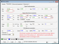
I picked a known decent driver from the Parts Express website:
Dayton Audio DC160-4 6-1/2" Classic Woofer Speaker-PE #295-309
Here is the data for spreadsheet (from manufacturer's data and Hornresp sealed box Vrc=15000 L):
Cone Dia.=13.2 cm - calculated from Sd=136.8 cm^2
Rx=~26.23 Ohms - (Hornresp Vrc=15000 L)
Fs=39 Hz
Re=3.4 Ohms
F1=25.6 Hz - (from Hornresp)
F2=56.4 Hz - (from Hornresp)
added mass=30 gm
Fres_loaded=25 Hz (wild guess)
Calculated results look close enough.
The calculator looks fine (apply ICG's caveats from Post #23). I still have a hard time believing, that your driver has a Mmd=366.07gm, that's way heavy for a 6.5" woofer. I'm not saying this is impossible, but just unlikely. If your measured T/S parameters are correct I'd suggest to use it only in a small sealed box.
Two more link, Brian Steele has a very nice website, he describes the higher power measurement in detail:
The Subwoofer DIY Page - Measurements
Take a look at his description of 'Passive Radiator Systems" too:
The Subwoofer DIY Page - Passive Radiator Systems
Regards,
Post #22: "...test this T/S calculator with a driver with known parameters as I don't have one around..."
I picked a known decent driver from the Parts Express website:
Dayton Audio DC160-4 6-1/2" Classic Woofer Speaker-PE #295-309
Here is the data for spreadsheet (from manufacturer's data and Hornresp sealed box Vrc=15000 L):
Cone Dia.=13.2 cm - calculated from Sd=136.8 cm^2
Rx=~26.23 Ohms - (Hornresp Vrc=15000 L)
Fs=39 Hz
Re=3.4 Ohms
F1=25.6 Hz - (from Hornresp)
F2=56.4 Hz - (from Hornresp)
added mass=30 gm
Fres_loaded=25 Hz (wild guess)
Calculated results look close enough.
The calculator looks fine (apply ICG's caveats from Post #23). I still have a hard time believing, that your driver has a Mmd=366.07gm, that's way heavy for a 6.5" woofer. I'm not saying this is impossible, but just unlikely. If your measured T/S parameters are correct I'd suggest to use it only in a small sealed box.
Two more link, Brian Steele has a very nice website, he describes the higher power measurement in detail:
The Subwoofer DIY Page - Measurements
Take a look at his description of 'Passive Radiator Systems" too:
The Subwoofer DIY Page - Passive Radiator Systems
Regards,
Thank you ICG for your time!
I've actually entered the value of ( Cone + 1/3 surround ) in the calculator. I think that's the best approximation.
Good point! I always put the multimeter to the most accurate level possible. And I always average my multimeter results.
NO! that method is ridiculous! I read the DC resistance of my driver using the DC resistance measurement on my multimeter, which I've calibrated before. The device adds near 0.4 ohm to the original number, Which I then subtract.
Yes, I measured it with 4.75 gr. and 9.5 gr. weights and both leaded to the Mms of 22.3 gr.
Yes, I understand this and I've attached weights to the cone using double-sided tape.
Good point!
Even worse is the multimeter, whose sensitivity goes lower as frequency decreases. I use online tone generators which are pretty accurate ( 1Hz accuracy ) Plus my DIY amp. And I calibrate the system down to 10Hz. I actually don't go anywhere below that. This is how I do the calibration: I measure the voltage across my 10 ohm resistor while playing a sine wave swipe down to 10 Hz. I draw its graph affect that in my results ( not in the amp source ).
I know, and mine don't have vents.
I post the parameters - you be the judge.
Regards, Ali.
At first, the calculation for the Sd ist just a very crude method......(membrane + 1/2 surround).
I've actually entered the value of ( Cone + 1/3 surround ) in the calculator. I think that's the best approximation.
Second, the usual additional +/- 1 digit tolerance (on top of the x% tolerance) makes a huge difference.
Good point! I always put the multimeter to the most accurate level possible. And I always average my multimeter results.
It's advised not to use that method to get the Re.
NO! that method is ridiculous! I read the DC resistance of my driver using the DC resistance measurement on my multimeter, which I've calibrated before. The device adds near 0.4 ohm to the original number, Which I then subtract.
3rds, ... If you divert from the added mass
Yes, I measured it with 4.75 gr. and 9.5 gr. weights and both leaded to the Mms of 22.3 gr.
Besides that, loose pennies or other stuff of that size tends to move, even if you can't see it, more critical at higher fs or excursion.
Yes, I understand this and I've attached weights to the cone using double-sided tape.
4th and most important for measuring such extreme drivers, the signal is way too weak for such extreme drivers because of the huge losses in the system, the speakers simply doesn't work properly at such levels. If you didn't know, the parameters drift with the power and excursion. You have to measure these subwooferchassis with much more power (i.e. ~1W at the driver for bigger high loss subwoofers).
Good point!
Most frequency generators can't deliver that power and you need an amplifier for it - but there's the next problem, with most amplifiers you can't get as low as 1 Hz. -35dB @1Hz is quite common, often even worse. If you try to compensate that with more gain...
Even worse is the multimeter, whose sensitivity goes lower as frequency decreases. I use online tone generators which are pretty accurate ( 1Hz accuracy ) Plus my DIY amp. And I calibrate the system down to 10Hz. I actually don't go anywhere below that. This is how I do the calibration: I measure the voltage across my 10 ohm resistor while playing a sine wave swipe down to 10 Hz. I draw its graph affect that in my results ( not in the amp source ).
Besides that, you should not measure chassis laying on the magnet if they have a vented magnet
I know, and mine don't have vents.
already one wrong measurement throws off the result.
I post the parameters - you be the judge.
Regards, Ali.
Hi tb46,
Thank you for checking that!
I didn't say The Mmd is 366 gr. ! It's actually 22.3 gr. How have you calculated that number???
I think there's something wrong with my Sd, Cmd and Vas as they are closely related. Even WinISD doesn't accept the numbers together. The wired part is that this faulty Cms ( and then Vas ) is calculated by the working calculator and the correct ( as far as I know ) input data.
I think I have to calculate the Vas and Cms myself.
And by the way, thanks for the links!
Regards, Ali.
I picked a known decent driver from the Parts Express ...Calculated results look close enough.
Thank you for checking that!
... I still have a hard time believing, that your driver has a Mmd=366.07gm.
I didn't say The Mmd is 366 gr. ! It's actually 22.3 gr. How have you calculated that number???
I think there's something wrong with my Sd, Cmd and Vas as they are closely related. Even WinISD doesn't accept the numbers together. The wired part is that this faulty Cms ( and then Vas ) is calculated by the working calculator and the correct ( as far as I know ) input data.
I think I have to calculate the Vas and Cms myself.
And by the way, thanks for the links!
Regards, Ali.
Hi 4392Viper,
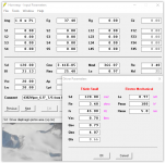
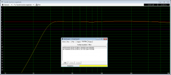
The Mmd I quoted is what Hornresp calcuates from the other T/S parameters (see attached). Somehow the Vas/Cms is just not correct.
Regards,
P.S.: Just noticed, the Dd entry in your WinISD screen is incorrect.
The Mmd I quoted is what Hornresp calcuates from the other T/S parameters (see attached). Somehow the Vas/Cms is just not correct.
Regards,
P.S.: Just noticed, the Dd entry in your WinISD screen is incorrect.
Attachments
Last edited:
Somehow the Vas/Cms is just not correct.
I guess so.
Just noticed, the Dd entry in your WinISD screen is incorrect.
It's auto - generated.
Regards, Ali.
Thanks tb46 for the instructions on numbers entry.
No, no. Sd and Dd are both auto - generated from the faulty Vas,Cms.
The Sd of 30cm² matches suspiciously an entered value of 6,2.. calculated down from 6,5" maybe?
No, no. Sd and Dd are both auto - generated from the faulty Vas,Cms.
Well, that's exactly the wrong way around - you can measure the Sd perfectly but not the Cms or Vas, esp. the Vas is directly dependent on the Sd! You HAVE to calculate it the other way around! Leave the other fields empty but the Sd is one of the most important values you have to enter correctly!No, no. Sd and Dd are both auto - generated from the faulty Vas,Cms.
Hi ICG,
Post #33: "...Sd is one of the most important values you have to enter correctly!"
As an aside, before Hornresp had a "Drivers Parameters" entry window, I always used the sequence of entering Sd first, then double-clicking on Cms, which would open a window asking: "Are you sure the value of Sd is correct?", after clicking "Yes" the "Calculate Cms" window would ask for the Vas. So, yes Sd has to be correct, and so does Vas...
Regards,
Thanks for the confirmation.
It's logical.
Vas = 1.18 * 340 * Sd² * Cms
While the first 2 factors (air density and speed of sound) are almost constants (at least for practical use), you could slove for Sd, for Cms or for Vas. Since Sd is the first and easiest to know (by mechanical/geometrical measurement), you are praktically always forced to have that value to calculate the others. The other way around you could easily verify the other parameters by solving for Sd since Sd is the only parameter which can not drift at all, at least for cone chassis, dome drivers etc. (some very rare others can though).
Thank you
I'm wondering if units are unintentionally mixed up anywhere - imperial into metric, micro into milli etc.
Anyway, in a couple days I'm gonna do some large signal test and do the calculations by hand and enter in the proper order into winISD, let's see what happens!
Regards, Ali.
I'm wondering if units are unintentionally mixed up anywhere - imperial into metric, micro into milli etc.
Anyway, in a couple days I'm gonna do some large signal test and do the calculations by hand and enter in the proper order into winISD, let's see what happens!
Regards, Ali.
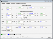
The woofers are healthy drivers, have nice appearance and good performance. They are capable of eating huge amounts of juice and not even getting warm.
---------------
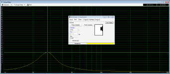
and After testing the T/S parameters by hand, it turns out they're pieces of trash to my job... with a Qts of 0.84 and a Vas of 13.8 lit. it seems there's no practical use for them except for a powerful car audio mid-bass driver firing in the trunk. The best tiny box I've done for it, though, is a 25 lit. ported box with a tuning of 35 Hz. Pictures attached.
Is there any better alignment for them or I hve to look for another pair of woofers?
Regards, Ali.
Attachments
I'm really sorry it turned out that way. Well, at least you've achieved to measure the parameters, it looks very reasonable, much more what I expected.
You could try to put them in a high-pass-sealed-enclosure, about 30l. The capacitor value can be simulated with WinISD pro. I'd expect it to go down to around ~30Hz, almost as deep as you wanted. The capacitor values could be very high though because of the low impedance. To save at the capacitors, you probably should wire the subwoofers in series.
Since you've already got the speakers, I'd say, it's worth a try, it will sound much cleaner than a ported enclosure and got much lower group delay. The max spl is ofc. lower than with a ported one.
Well, at least you've achieved to measure the parameters, it looks very reasonable, much more what I expected.You could try to put them in a high-pass-sealed-enclosure, about 30l. The capacitor value can be simulated with WinISD pro. I'd expect it to go down to around ~30Hz, almost as deep as you wanted. The capacitor values could be very high though because of the low impedance. To save at the capacitors, you probably should wire the subwoofers in series.
Since you've already got the speakers, I'd say, it's worth a try, it will sound much cleaner than a ported enclosure and got much lower group delay. The max spl is ofc. lower than with a ported one.
Thanks ICG,
Yes, I'm happy I've finally measured it right.
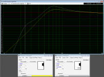
Yes! I finally made it to the next design!
Turns out it's an 18.5 lit. sealed box and turns out it has awesome group delay characteristics. also with some EQ, it can achieve F-10 = 21 Hz at reasonable power consumption.
Why high-pass when I can go lower? There's no need for caps - All the caps I need are back there in the PSU!
Besides, I have some decent Parametric EQ in my laptop from where I can apply an 8th order high-pass @ 30 Hz, which is much better than the one shown in the graphs.
Regards, Ali
Well, at least you've achieved to measure the parameters, it looks very reasonable, much more what I expected.
Yes, I'm happy I've finally measured it right.
Yes! I finally made it to the next design!
Turns out it's an 18.5 lit. sealed box and turns out it has awesome group delay characteristics. also with some EQ, it can achieve F-10 = 21 Hz at reasonable power consumption.
You could try to put them in a high-pass-sealed-enclosure, about 30l. The capacitor value can be ...
Why high-pass when I can go lower? There's no need for caps - All the caps I need are back there in the PSU!
Besides, I have some decent Parametric EQ in my laptop from where I can apply an 8th order high-pass @ 30 Hz, which is much better than the one shown in the graphs.
Regards, Ali
Attachments
- Status
- This old topic is closed. If you want to reopen this topic, contact a moderator using the "Report Post" button.
- Home
- Loudspeakers
- Subwoofers
- Passive Radiator Compromises