SS15MOD - TH 15" flat response
Hello all,
Time to post some results, but before, I'd like to say thanks to all guys who have been supporting / teaching / encouraging me to learn more about TH design.
After some benchmark between lots of different cab I decided to choose TH one due to the large documentation available for design but also due to good results between simulation and real worlds.
The base design is the SS15 published by Jbell (He has one sheet build constrain, I'm not )
)
Single sheet TH challenge
or TH18 published by Xoc1 (designed for 18" drivers based on Danley's design TH118 that is also based on previous 15" design TH115)
TH-18 Flat to 35hz! (Xoc1's design)
They have the same base design in terms of fold.
Project targets:
Low frequency <40Hz for a single cab
High frequency > 100Hz
Volume < 300 L (reduced from 450L once my current T18 clone cab has 300L with 18” driver and I swapped from 18" to 15")
Single driver
SPL@1m > 98dB
I chose Brazilian driver Snake HPX2150 15” and I also forgot about 18” once I confirmed I could reach my target with 15” one with more compacted size.
Bellow you can find Thielle/Small parameters in comparison with SS15’s driver (Eminence) and also THAM15’s driver (B&C):
The design was started using the image below to find the best targets for the cab.
The S1 is a results of driver compression ratio (cone area dived by throat area).
Detail about the others parameters see here (credits to soho54):
Hornresp for Dum... hmm... Everyone - Page 2 - Home Theater Forum and Systems - HomeTheaterShack.com
Like a DOE (design of experiments) I covered the ranged bellow:
Compression ratio: 1:1 till 2,5:1
Note: I didn’t went higher once the driver isn’t stiff enough and the motor strength (BL^2/Re) isn’t that high too.
Horn Length: 250cm till 350cm
Horn expansion angle: 0 degree till 5 degree
The best option I found was:
Compression ratio 2:1
Horn Length: 260cm
Horn expansion angle: 3 degree
Hornresp parameter for base design.
S1: 440 L12: 20 S2: 493,68 L23: 100 S3: 760,92 L34: 120 S4: 1081,71 L45: 20 S5: 1134,75
The next step was to install Solidworks to build the cab thru automatic folding process using parametric sketch.
In sequence I also implement an automatic unfolding process. This is very important to guarantee reliability on the hornresp simulation. I used soho54 method that is called “advanced centerline method”.
Using parametric CAD software makes things easier when they are well implemented.
Next, I tryed to add the second horn expansion:
Horn expansion angle: from 3 degree till 24 degree.
The best results condifering 2nd expansion was: 6 degree and 12 degree
Here are my proposals:
Proposal A (HxDxW 762 x 630 x 550 = 264,5L)
Proposal B (HxDxW 776 x 625 x 550 = 267,1L)
Proposals A and B over righted @ 600W
Which one would you guys pick up to build?

Hello all,
Time to post some results, but before, I'd like to say thanks to all guys who have been supporting / teaching / encouraging me to learn more about TH design.
After some benchmark between lots of different cab I decided to choose TH one due to the large documentation available for design but also due to good results between simulation and real worlds.
The base design is the SS15 published by Jbell (He has one sheet build constrain, I'm not
)Single sheet TH challenge
or TH18 published by Xoc1 (designed for 18" drivers based on Danley's design TH118 that is also based on previous 15" design TH115)
TH-18 Flat to 35hz! (Xoc1's design)
They have the same base design in terms of fold.
Project targets:
Low frequency <40Hz for a single cab
High frequency > 100Hz
Volume < 300 L (reduced from 450L once my current T18 clone cab has 300L with 18” driver and I swapped from 18" to 15")
Single driver
SPL@1m > 98dB
I chose Brazilian driver Snake HPX2150 15” and I also forgot about 18” once I confirmed I could reach my target with 15” one with more compacted size.
Bellow you can find Thielle/Small parameters in comparison with SS15’s driver (Eminence) and also THAM15’s driver (B&C):
An externally hosted image should be here but it was not working when we last tested it.
The design was started using the image below to find the best targets for the cab.
An externally hosted image should be here but it was not working when we last tested it.
The S1 is a results of driver compression ratio (cone area dived by throat area).
Detail about the others parameters see here (credits to soho54):
Hornresp for Dum... hmm... Everyone
- Page 2 - Home Theater Forum and Systems - HomeTheaterShack.comLike a DOE (design of experiments) I covered the ranged bellow:
Compression ratio: 1:1 till 2,5:1
Note: I didn’t went higher once the driver isn’t stiff enough and the motor strength (BL^2/Re) isn’t that high too.
Horn Length: 250cm till 350cm
Horn expansion angle: 0 degree till 5 degree
The best option I found was:
Compression ratio 2:1
Horn Length: 260cm
Horn expansion angle: 3 degree
Hornresp parameter for base design.
S1: 440 L12: 20 S2: 493,68 L23: 100 S3: 760,92 L34: 120 S4: 1081,71 L45: 20 S5: 1134,75
The next step was to install Solidworks to build the cab thru automatic folding process using parametric sketch.
An externally hosted image should be here but it was not working when we last tested it.
In sequence I also implement an automatic unfolding process. This is very important to guarantee reliability on the hornresp simulation. I used soho54 method that is called “advanced centerline method”.
An externally hosted image should be here but it was not working when we last tested it.
Using parametric CAD software makes things easier when they are well implemented.
Next, I tryed to add the second horn expansion:
Horn expansion angle: from 3 degree till 24 degree.
An externally hosted image should be here but it was not working when we last tested it.
An externally hosted image should be here but it was not working when we last tested it.
The best results condifering 2nd expansion was: 6 degree and 12 degree
Here are my proposals:
Proposal A (HxDxW 762 x 630 x 550 = 264,5L)
An externally hosted image should be here but it was not working when we last tested it.
Proposal B (HxDxW 776 x 625 x 550 = 267,1L)
An externally hosted image should be here but it was not working when we last tested it.
Proposals A and B over righted @ 600W
An externally hosted image should be here but it was not working when we last tested it.
Which one would you guys pick up to build?
Last edited:
It's still not fully clear for me if the hornresp has accurate simulation for cone displacement and how this result can be linked to music wave once you don't play pure sine waves.
Proposal A - Cone displacements @ 800 W/4,7ohm
Proposal B - Cone displacements @ 800 W/4,7ohm
Proposal A - Cone displacements @ 800 W/4,7ohm
An externally hosted image should be here but it was not working when we last tested it.
Proposal B - Cone displacements @ 800 W/4,7ohm
An externally hosted image should be here but it was not working when we last tested it.
Here an image to compare SPL@1w/1m the FR from SS15, THAM15 and SS15MOD-B (my proposal for HPX2150 drive).
An externally hosted image should be here but it was not working when we last tested it.
Both designs are missing "cone compensation", so the frequency response at the upper end of the passband (where the notch appears) is likely to be a bit different by a few dB.
Hi Brian,
Here are additional simulation with 3 different compression ratios.
The new question emerge: Is the HPX2150 drive able to manage 3:1 as compression ratio?
Once I'm no able to answer I was being more careful about compression ratio.
Note: Increasing compression ratio also requires to increase horn angle for the first expansion from 3 degrees to 4 degrees and 5 degree respectively to be able to keep reduced size. But even doing that, higher compression ratio will increase a little the cab volume to cover the same low frequency response. The good side is it will give a lot more high frequencies as you pointed and also helps to reduce max cone displacement.
An externally hosted image should be here but it was not working when we last tested it.
Hi Brian,
Here are additional simulation with 3 different compression ratios.
I'm not referring to compression ratios. I'm referring to either adjusting the model to include the volume of air contained by the driver's cone (Vtc and Atc), or adjusting the horn's layout so that the impact of this volume on the performance of the horn is minimized.
I'm not referring to compression ratios.
True, I worked too much yesterday and was publishing late at night so was my mistake. Anyway the CR = 3 looks good associated to 2nd expansion.
I'm planning to implement cone correction. Is there any guide for it? or it's just to add material with the cone volume aligned to the driver?
I think this design is the easiest one to implement.
An externally hosted image should be here but it was not working when we last tested it.
Anyone have idea to add grip? i think this cab will have more then 50kg so will not be easy to move it.
Hi Lordsansui
Good work. This is the DIY forum after all and its good to see you are 'Doing It for Yourself'!
As for the cone compensation, I would not recommend the extra timber as it reduces volume and increases weight.
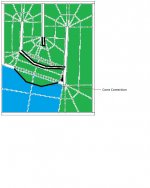
I have sketched out a quick mod of your layout. The cone correction line should be set out to suit your speaker cone, and relates to the cross sectional area of the air in the speaker cone. The volume also reduces the area at S4.
The cone correction is not to increase the compression ratio. It makes the ratio correct to your sim, therefore increasing the accuracy.
Good work. This is the DIY forum after all and its good to see you are 'Doing It for Yourself'!
As for the cone compensation, I would not recommend the extra timber as it reduces volume and increases weight.
I have sketched out a quick mod of your layout. The cone correction line should be set out to suit your speaker cone, and relates to the cross sectional area of the air in the speaker cone. The volume also reduces the area at S4.
The cone correction is not to increase the compression ratio. It makes the ratio correct to your sim, therefore increasing the accuracy.
Attachments
Xoc1,
Should I redo all parametric fold and unfold sketch to do it or I can change just the areas as you indicated? I think just changing that areas it will create the effect indicated below. The path length will increase but at the cost of add restriction.
The compression ratio was my mistake "reading" once I was sleepy. But talking about it, using under 800W power, do you think a CR 3:1 would be a problem for not special cone made driver?
An externally hosted image should be here but it was not working when we last tested it.
As for the cone compensation, I would not recommend the extra timber as it reduces volume and increases weight.
Agreed.
The cone correction is not to increase the compression ratio. It makes the ratio correct to your sim, therefore increasing the accuracy.
Exactly. To address it, you either have to
(1) adjust the sim to take cone correction into consideration (usually done by setting Atc~Sd and increasing Vtc to account for the extra volume of air that sits between the cone and the entrance to the horn @S2), or
(2) modify the layout of the horn @S2 to compensate for that volume
The cone correction and bracing will be the final part, together with plan.
Some feedbacks regarding hornresp cone displacement accuracy will help me a lot to conclude this project, I ready a lot of posting telling that the simulation show higher displacement than reality.
The second point is about compression ratio for common cone material, 15" drive can manage 800W with compression ratio 3:1 ?
Regarding those two doubts I prepared a third proposal (C). The compression ratio was increased from 2:1 to 3:1, first horn expansion was increased from 3 degrees to 4,5 degrees and the 2nd expansion increased to 32 degrees. As a results the SPL rise and cone displacement reduces. The price was loosing some low frequency as a trade off.
An externally hosted image should be here but it was not working when we last tested it.
The cone correction and bracing will be the final part, together with plan.
Why? All you have to do is fill in Vtc and Atc and the sim will be as accurate as it's going to get. You could probably even get the cone shape correct by using Ap1 and Lp if you want to get as accurate as possible. I haven't actually tried this but it looks like to could be used to accurate describe the cone shape. Either way, it's pure negligence no not fill in Vtc and Atc. In most cases it doesn't matter much but if this is something you are actually thinking of building you should definitely have the throat chamber included in the sim.
Some feedbacks regarding hornresp cone displacement accuracy will help me a lot to conclude this project, I ready a lot of posting telling that the simulation show higher displacement than reality.
Unless you can measure cone excursion accurately I wouldn't worry about it. Even if you could I don't think Hornresp's predictions are going to be off by much. We all use Hornresp's predictions as the best guess we have.
The second point is about compression ratio for common cone material, 15" drive can manage 800W with compression ratio 3:1 ?
You can look at pressure in Hornresp. Then you can compare that with pressure in other similar simulated designs with similar drivers. If the compared design is well vetted and known to be ok with the pressures then your design will likely also be ok.
Regarding those two doubts I prepared a third proposal (C). The compression ratio was increased from 2:1 to 3:1, first horn expansion was increased from 3 degrees to 4,5 degrees and the 2nd expansion increased to 32 degrees. As a results the SPL rise and cone displacement reduces. The price was loosing some low frequency as a trade off.
Look at the pressure on the cone at xmax with all 3 proposals in Hornresp. I'm not sure why you ask for opinions about this stuff when you can just look in Hornresp and it will show very clearly how much pressure each design puts on the cone. Make sure you check at xmax, not at 1 watt.
Speaking of 1 watt, I'm pretty sure your 1 watt sims are still not 1 watt. I told you before not to sim everything at 2.83V, this is VERY different than 1 watt unless the speaker's Re is exactly 8 ohms.
Last edited:
Speaking of 1 watt, I'm pretty sure your 1 watt sims are still not 1 watt. I told you before not to sim everything at 2.83V, this is VERY different than 1 watt unless the speaker's Re is exactly 8 ohms.
The only point I disagree with. All that you'd be accomplishing with this is having HornResp sim the efficiency of your sim referenced to the driver Re, not its sensitivity. As basically all pro audio amplifiers these days can meet or exceed their 8 ohm ratings at lower impedances, the sensitivity rating is more important and certainly more indicative of the output you can actually achieve with your build.
Why? All you have to do is fill in Vtc and Atc
Each cab has different geometry so I can do this at the end, with cone correction added there is no reason to add Vtc/Atc.
You can look at pressure in Hornresp. Then you can compare that with pressure in other similar simulated designs with similar drivers. If the compared design is well vetted and known to be ok with the pressures then your design will likely also be ok.
I could do it for sure but I don't have database available to compare with, so this is the reason I'm asking for help. The only one information I have close to this one is the SS16 with eminence drive but it's just 450 W and the compression ratio is 1,79
Look at the pressure on the cone at xmax with all 3 proposals in Hornresp
Without cone material specification on hand it's worthless to look at numbers. Some guys here have more experience building cabs than my age and this helps a lot.
I know 2.83V is not 1 watt, but sometimes we are lazy and the major part of the people use it as 1 W wrongly, so you can cover your eyes for this
The only point I disagree with. All that you'd be accomplishing with this is having HornResp sim the efficiency of your sim referenced to the driver Re, not its sensitivity. As basically all pro audio amplifiers these days can meet or exceed their 8 ohm ratings at lower impedances, the sensitivity rating is more important and certainly more indicative of the output you can actually achieve with your build.
If the intent is to see how they compare with equal power (which is almost always the intent when someone simulates everything at 2.83V), then the intent has not been satisfied because they are not comparing equal power.
In this case specifically I KNOW he intended to sim at equal power because he specifically said all the sims were shown at 1 watt, but that isn't true, they were shown at 2.83V so none of them were actually shown at 1 watt.
If the intent is to see how they compare with equal power
"Equal power" is a myth. The system's impedance VARIES with frequency. This is true for basically EVERY subwoofer system. So setting a "1 Watt" voltage without a reference frequency in reality makes absolutely no sense. And lets not forget too that there's a pretty good chance that the impedance of the subwoofer through its operating range will never hit as low as Re, so using Re as a the reference impedance for "1 Watt" may likely be incorrect too. Now, if you were to say "1 Watt" at a specific frequency, then that gets a little better, but who measures subwoofers based on their 1 Watt output at a specific frequency?
Secondly, I'd love to hear if anyone has ever seen a pro audio amplifier where the gain is set in terms of output wattage instead of output voltage, particularly considering that the output wattage will be based on the load's impedance and the output voltage will not be. Basically all pro audio amps can be considered as voltage sources once the load is above their minimum rated impedance.
In summary, comparing alignments based on an arbitrary "1 Watt" that's basically determined at what voltage is required to produce 1 Watt across the driver's Re simply makes no sense when the real-world use of these alignments is taken into consideration.
"Equal power" is a myth.
...
Sure the impedance curve is a roller coaster. But the intent of putting a sensitivity rating on a sub is to compare to other products. And the intent in trying to compare different designs in sims at "1 watt" or 2.83 volts is to compare to other designs.
Comparing at a single frequency doesn't make any sense.
Comparing every product at the same voltage doesn't make any sense.
So how can you compare?
You can take the minimum impedance in the passband, reference your voltage to that impedance and call it "1 watt". It's not 1 watt everywhere in the passband but it's as close as you can possibly get to an equal power equivalency test.
I'll say it again - for an equivalency comparison, comparing everything at 2.83V makes absolutely no sense at all, that makes things decidedly unequivalent. The most equivalent power level you can possible hope for is voltage based on watts referenced to minimum impedance in the passband.
A better way to compare would be frequency response at max spl, but that comparison is not small signal so it's fraught with complication.
Comparing every product at the same voltage doesn't make any sense.
Yes it does. And that's why basically every audio company quotes a 2.83V reference for their speaker products. It takes literally seconds with a voltmeter to check the output voltage from an amp to confirm that it's 2.83V. And amplifier gain is adjusted by Volts, NOT Watts. I don't have to sit down and work out what voltage I have to set the amplifier to in order to meet your "1 Watt" reference, which apparently has now been changed, by your subsequent note below, LOL. So which should I use now - Re, or measured minimum impedance in the passband?
You can take the minimum impedance in the passband, reference your voltage to that impedance and call it "1 watt". It's not 1 watt everywhere in the passband but it's as close as you can possibly get to an equal power equivalency test.
... which now requires taking an impedance response curve and reading off Rmin, then using that to calculate what "1 Watt" would be at that frequency (and that frequency alone, because impedance will be different at every other frequency) rather than simply setting the voltage at the amp to 2.83 V. How is that more sensible as a reference?
- Status
- This old topic is closed. If you want to reopen this topic, contact a moderator using the "Report Post" button.
- Home
- Loudspeakers
- Subwoofers
- TH 15" flat response to 35Hz (-3dB) - By LORDSANSUI