")
in listening tests the pair of 10cm ports are quite acceptable, but careful flaring is needed,
of course you can increase the port area.
with 5kw and sine tones you could create audible port noise,
remember these are suggested design's to get you going, not an ultimate design guide.
i'm looking forward to seeing some creative DIY designs using this driver,
2xSTW and 2x18" PR would be interesting and force canceling,
the mounting with 2 drivers and 4PR would lead to a very cool looking sub.
my personal preference in sound quality would still be sealed though!
Such tests are best done around the resonance frequency (25 Hz for this woofer), as impedance peaks around there and dissipation will be low.did anyone check the frequency on this 176volt run? fs?
The impedance is plotted on a hard to read scale, though it seems to be around 35 ohms at 20 Hz. That would lead to a current of 176 / 35 = 5,0 A. Voltage and current are not in phase, so dissipated power would be lower than just the product of voltage and current (880 VA).
Last edited:
ok, this is off-the-record data, not published spec.
below is some data showing the driver can achieve the displacements talked about,
bear in mind this is not an final production level driver, it's a beat up test unit, the production stock is actually better, but due to demand we don't have one to spare!
the odd looking gaps in the data is where the limits were adjusted and the system re-enlarged the signal.
there is a slight offset in the displacement data, due to the laser shifting slightly during the test. this driver puts a huge amount of force into the test rig.
also bear in mind that the RMS voltage on the graphs is not comparable to RMS sine signal. sine signal has a much lower peak to RMS ratio compared to the klippel stimulus voltage.
but from the graph you can see that 300V peaks do no lasting damage.
driver was connected with the coils in parallel !
Last edited:
For example...
here is a thread, albeit in german, where someone klippel`d 3 drivers:
IMD, HD, Xmax und Klippel - Vergleich und Bewertung von 3 Chassis - DIY-HIFI-Forum
- Monacor SP-8/150PRO
- Visaton GF 200 (coils in series)
- Faital Pro 8PR200
Calculated xmax:
- Monacor: +-6mm
- Visaton: +-6mm
- Faital: +-5.15mm
(voice coil height/2 – top plate thickness)
(Faital adds another 1/3 top plate thickness)
Measured xmax(10%THD):
Monacor: Xmax10 = 2.1 mm
Visaton: Xmax10 = 3.4 mm
Faital: Xmax10 = 4.5 mm
That isn't what I was meaning.
None of the manufacturers have exaggerated their xmax values based off of the purely mathematically derived value. Yes, they all fall grossly short of being linear out to that amount of excursion but most likely because the suspension/soft parts can't support that much in an adequate fashion.
By lying I mean that the mathematically derived value would = 5mm, but the manufacturer says it has 10mm, just to sound impressive.
Isn't adding 1/3 or 1/2 the gap height exaggerating?
10% THD is a fairly arbitrary figure to define a limit.
To be honest the fascination with excursion is a little odd if we think about it logically?
CEA 2010 or similar might be a better metric.
I'd like to see someone take it back to practical aspects.
E.g. who cares if it's a 15" or 4" driver as long as it produces the requires SPL at required distortion limit in a given cabinet size.
The practical aspects are cabinet size and useable SPL. Maybe with available amp power as a third boundary.
In reality it shouldn't matter if it's a long throw 8", short throw 18" or array of 16pc 2" as long as the performance in a particular physical package is as required.
That isn't what I was meaning.
None of the manufacturers have exaggerated their xmax values based off of the purely mathematically derived value. Yes, they all fall grossly short of being linear out to that amount of excursion but most likely because the suspension/soft parts can't support that much in an adequate fashion.
By lying I mean that the mathematically derived value would = 5mm, but the manufacturer says it has 10mm, just to sound impressive.
At least I know Aura did it.
50.8mm(He) - 25.4 = 25.4mm (P-P xmax)
While quoting 50mm P-P
Aurasound NS18-992-4A 18" Subwoofer
Peerless says neodymium "is unstable and loses strength as temperature increases" in their description of this driver. Comment?
Having hammered some neodymium drivers really quite hard with some fairly large amplifiers (anything up to and including a Crown MA12000i), I can say that I haven't noticed any problems.
Chris
What is "this driver" ?Peerless says neodymium "is unstable and loses strength as temperature increases" in their description of this driver. Comment?
Technically, the statement that neodymium "is unstable and loses strength as temperature increases" is correct, but loudspeakers normally use neodymium iron boron alloys with terbium and dysprosium, rare earths necessary for neodymium magnets that require high heat resistance. Formulations are available with working temperatures of around 240C, comparable to ferrite magnet formulations.
The availability of terbium and dysprosium can drive the cost of "neo" drivers quite high.
Art
loudspeakers normally use neodymium iron boron alloys with terbium and dysprosium, rare earths necessary for neodymium magnets that require high heat resistance. Formulations are available with working temperatures of around 240C, comparable to ferrite magnet formulations.
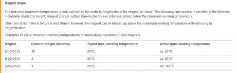
From what i've found here, FAQ - Frequently asked questions about super magnets and magnetism - supermagnete.frtemperature supported depend too of the ratio between base surface and his height.
It seems so to depend in fact too of how is built the speaker. Neo magnet are "smaller" so, it make new arrangement possible, as a disk in bellow the gap inside the pole piece. So that it's not a tall magnet needed.
Real demagnetisation VS temperature depend of the magnet shape. Tall magnet support better temperature than disk. So using disk in the pole piece, choosing neo magnet with higher temperature grade is the way to go (N grade magnet beeing the lower temp grade, 80°C vs 230°C for AH grade magnet).
But with old school construction, replacing ferrite (arround the pole piece) with multiple neo cylinder, temperature grade of neo magnet is less mandatory. For diy, using lot of cylinders of available N grade magnet seems so the way to go.
Just found info and calculators here : Temperature and Neodymium Magnets
EDIT : i OVERsimplified the problem. The full magnetic circuit need to be taken in account to determine temperature VS loose...too much for me...
Attachments
Last edited:
With eminence's new releases, this thing is just sort of meh. Check out the lengthy thread over at AVS, and Ricci did a write-up over at data-bass on this driver
I'll take a look at AVS. Read the DB review a while ago, cant recall it being bad. What Eminence 15" model would go up against the STW?
Thanks
I'll take a look at AVS. Read the DB review a while ago, cant recall it being bad. What Eminence 15" model would go up against the STW?
Thanks
The reviews aren't bad, the driver simply doesn't do what it's advertised to do. If you need an absurdly small box and a bridged clone amp, this driver can do that. But in no way will it do it's excursion claims etc. It eats power...
As far as Eminence 15s....haven't looked at them in a while. But the nsw series of drivers looks very good. If the 18" actually gets released into the wild I'd expect it's pricing to be similar to the peerless driver.
Thanks. Just read 6 of the last pages (out of 20) on the AVS forum. As ashamed as I am to admit it, I was one over by what i now see clearly as marketing nonsense! Seems the STW is capable of about 20mm xmax. It's a future project I'm considering, definitely scrapping considering the STW.
- Status
- This old topic is closed. If you want to reopen this topic, contact a moderator using the "Report Post" button.
- Home
- Loudspeakers
- Subwoofers
- New Peerless STW350 subwoofer on the horizon...