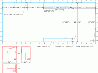
1)Yes, many do just experiment with software. Typical "tunnel" end fire are not enclosed in an actual tunnel, the output goes left and right as well as forward and back, creating lobes representative of the various spacings and overall length.1)One of the biggest questions now is to understand the spacing between the two rows of the array. It seems like many just experiment with simulating expected results with software.
2)Is there a way to actually use math to calculate it (at least approximately)?
3)Would that space between L and R rows change depending on using front-loaded or horn-loaded subwoofers?
4)The answer to the question above would help me decide on the importance of placing the cabinets “flush” against the wall. One major factor is the spacing between two rows in the array. With cabinets flush against trailer’s inside fenders, I would have up to 17” of separation between L and R array rows. With cabinets raised above fenders, flush against the wall, the separation between L and R array rows can be up to 34” total. But how much of separation do I want? And will that distance change depending on if the arrays are single-height stacked or 4x4-side stacked?
5)What is the reason to place cabinets “flush” against trailer walls anyway? Is it to increase the distance between the L and R array rows? Or is it just to contain the boundary?
6) If the reason is boundary containment, is it even applicable with these horn-loaded cabinets, as they have some inherent directivity by design?
7)Another way to contain the boundary would be setting cabs flush against fenders AND building an additional reinforcement wall behind them (leaving 8-9 inches to the trailer wall at the same width as fenders). Would that take care of the problem? I would basically be building a “box around the array”. Plywood on the floor, sturdy “lid” on top of the tunnel, “cap” on back end, and then maybe some “side walls” that go the length of the array would take care of the L and R sides?
8)I wanted to confirm my understanding of the proposed option on how to get around the fenders – You could stack most of the subs upright, but place a pair the thinner dimension above the wheel wells, and just adjust delay accordingly, I think I understood that as sitting most cabs upright on the floor, with a couple cabs flipped on their sides on top of the fenders? That would change the delay of course. But wouldn’t that create some strange phasing coming out of horn mouths?
9)I also wanted to confirm my understanding of using the delay with this tunnel-fire array. The idea is to space the cabinets by the length of 1/4-wave of XO frequency (so 34” for 100 Hz crossover). The delay would be calculated using standard speed of sound, with the furthest cabinets having 0 delay, increasing delay on each L-R cabinet pair based on the distance?
10)So, this is where my question about measuring distances originated from, I meant distances between cabs as they are lined away from the “end” of the array. Since the cabs are not pointing forward, they are pointing sideways and two rows are firing towards each other, I wanted to know the point of measurement for delay. With single boxes stacked upright, the first cabinet has 0 delay, so do I set the delay for other cabs based simply on distance from the center of one mouth to the center of another mouth?
11)I think the comment about “10 inches in from the flat part of the horn” would be applicable if the cabs within the array were oriented front-to-back and not side-to-side?
12)Also wanted to follow up on a quote by Benett Prescott from B&C in that Carrie Underwood’s array thread, “The spacing between subs in an end-fire subwoofer array (which is certainly what we're dealing with here) determines the maximum frequency that the array will be effective to. The overall length of the array determines the minimum frequency” – he was sorta talking about regular end-fire arrays as opposed to tunnel-fire, but I wonder if this is also applicable – as it will also help me determine if I want to array them as single upright boxes (with 8 delay zones), or as 4x4 clusters (with 2 delay zones, I think, since the 4 horn mouths would couple and work as one point source).
2)Yes, the various simulation programs use math.
3)No.
4)My concern with your actual 4 sided "tunnel" is the extreme SPL developed at the "mouth" end, a "too small" exit may result in extreme pressure build up that could cause air-nonlinearity distortion, and potentially result in more pressure on the cones nearer to the exit, causing them to buckle or rip.
5)To increase the tunnel width (see 4) and allow gear storage between. The top of the tunnel should be covered to prevent small room modes from sapping energy that you want out of the trailer, not bouncing around within.
6)Any directivity is being put in the tunnel. As well as the sound waves going forward in the tunnel, gaining SPL with the combined output of the progressively delayed outputs, half the output will go to the back and reflect forward, which may considerably reduce output compared to a conventional set up, due to phase cancellation.
7) Too much to consider prior to doing a "proof of concept" test.
8) As long as delay is set to time of flight from the acoustic center of the cabinet, the only "strange phasing" will be as described in response 6.
9)34" is the (maximum) center to center inter-cabinet distance which will still maintain 1/4 wavelength at 100 Hz. C to C spacing determines the delay needed between cabinets- 2 feet Cto C is roughly 2ms, 3 feet, roughly 3ms, etc.
10)The first delay should be equal to the C to C distance between the first and second cabinet's axial center point of acoustical output at the higher crossover frequency.
11) The axial center point of acoustical output at the higher crossover frequency will be the same in either orientation, approximately where the center line between your directional arrows in the diagrams are.
12)As Bennett points out, more delay zones will improve the higher frequency (maximum frequency that the array will be effective to) resolution.
That said, the concerns in my responses 4 and 6 are not trivial, I'd suggest some proof of concept trials before cutting any wood. You can use unused cabinets as the top and back of the tunnel, short out the speakers or they will act as resonators.
Art
I absolutely agree with the “proof of concept” testing prior to any major modifications.
I hear your concern with the 4-sided “tunnel”. Especially if that “tunnel” is made of single cabs stacked upright in a long line of 8 (minimum 16 feet long “tunnel”). I can see how the SPL at the exit from the “tunnel” would be quite high. High SPL at the mouth is fine in terms of response. But I didn’t think about air-nonlinearity distortion and would like to avoid ripping drivers.
Using arrays made of 2-cabs-tall (stacked on sides), or 2-cabs-tall (stacked upright), or 4-cabs-tall (stacked on sides) would reduce the length of the “tunnel”. The “tunnel” length would be reduced to 12, 8, or 6 feet respectively and the height would increase to 6, 4, or 8 feet respectively.
Tunnel stacking options (per each side):
* M-T-M = mouth-to-mouth side stacking
* T-O-B = top-on-bottom side stacking
(A) 1x8 – cabs upright, 1 high, 8 long = tunnel is 16’ long, 3’ tall, 8 delays
(B) 2x2 – cabs upright, 2 high, 4 long = tunnel is 8’ long, 6’ tall, 4 delays
(C) 2x2 – cabs on side T-O-B, 2 high, 4 long = tunnel is 12’ long, 4’ tall, 4 delays
(D) 2x2 – cabs on side M-T-M, 2 high, 4 long = tunnel is 12’ long, 4’ tall, 2 delays
(E) 4x2 – cabs on side T-O-B, 4 high, 2 long = tunnel is 6’ long, 8’ tall, 2 delays
(F) 4x2 – cabs on side M-T-M, 4 high, 2 long = tunnel is 6’ long, 8’ tall, 0 delays
So there are definitely several options to experiment with the length and the height of the “tunnel” and the resulting number of delay zones. What would be the logical order to try those options in? There are a couple of other possible arrangements (such as 2 cabs sideways on fenders) and I will try to post some diagrams later…
I also wonder how drivers survive in the specialty-made forward-steering multidriver boxes, like JBL PD125 described and pictured in this article: https://www.jblpro.com/ProductAttachments/PD_LF_TechNote.pdf
Wouldn’t my “box” inside of the trailer be just a scaled-up version of the above enclosure?
Any directivity is being put in the tunnel. As well as the sound waves going forward in the tunnel, gaining SPL with the combined output of the progressively delayed outputs, half the output will go to the back and reflect forward, which may considerably reduce output compared to a conventional set up, due to phase cancellation.
That was the reason I was asking about “capping” one end. I would have to draw a little picture to try and wrap my mind around how sound waves would travel and bounce, and what kind of delays and phase cancelation would result. I can’t do it in my head, but I know it can be done.
In general, I was curious how making a “cap” and a “lid” would affect this array. On one hand, arrays similar to Carrie Underwood’s tour are deployed with both front and rear ends open and no lid on top. Although, there was a stage directly above that array, I would imagine that the stage would vibrate to hell if there was much directivity upwards from the array and that tells me that the array was designed to mostly fire out of the front end (mostly being the key word).
So if the point of such an end-fire (or tunnel-fire) forward-steered bass array is to reduce the bass energy in all directions other than the front end, I’m sure there will still be “some” energy going in all directions, but it will be greatly reduced compared to what’s coming out of the front end. Using that logic, maybe the reflections are not that much of an issue? Would they be significant enough? Maybe the only way to find out is to try it. But it would be nice to try and predict the results.
And then we have those JBL PD-series boxes that were designed with multiple drivers firing into a “tunnel” inside of the cabinet. Is it really all that different than a “tunnel” inside of a trailer? Seems like the box inside of the trailer would be just a scaled-up version of the cabinet. I realize that sound pressures are somewhat different. But the enclosure size is much smaller too. I’ve even seen similar designs with car audio (I know, I know).
1) The upper hemispherical radiation of the Carrie Underwood under stage "tunnel" end fire is not enclosed, there is a gap between the stage and the cabinets. That gap is relatively short compared to the upper wavelength at the crossover frequency, so is not a great issue, though also is not the preferred deployment compared to flying.1)So if the point of such an end-fire (or tunnel-fire) forward-steered bass array is to reduce the bass energy in all directions other than the front end, I’m sure there will still be “some” energy going in all directions, but it will be greatly reduced compared to what’s coming out of the front end. Using that logic, maybe the reflections are not that much of an issue? Would they be significant enough?
2)And then we have those JBL PD-series boxes that were designed with multiple drivers firing into a “tunnel” inside of the cabinet. Is it really all that different than a “tunnel” inside of a trailer?
Reflections in an enclosed tunnel, or a small room (like your trailer) will be problematic. The "problem" is interesting- the cabinets at the closed end of the tunnel have no back reflection issue, but the cabinets progressively have a greater rear reflected length. However, the reflected wave is progressively diminished by the inverse distance law, dropping 6 dB per doubling of round trip distance in comparison to the forward directing wave, so the cancellations may also be diminished in amplitude.
2) There are no capped end four sided "tunnels" in the JBL PD-series boxes.
Another possible "trailer tunnel" configuration would be cabinets on either side facing in, 36" direction fore and aft, with cabinets on top facing down. An alignment strip of wood (or some type of interlocking foot/receiver arrangement) would be needed to keep the top cabinets from "dancing" and partially toppling into the tunnel during operation, but it would be fairly little work to tip half the cabinets to either side, leaving about an 18" aisle down the center for gear storage.
The above arrangement would probably be the quickest to set up as a proof of concept test.
Art
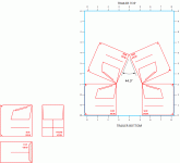
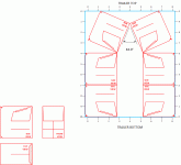
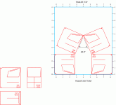
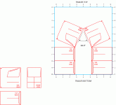
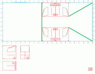
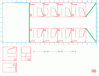
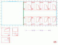
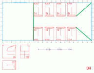
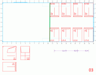
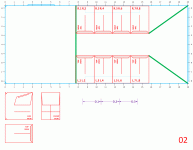
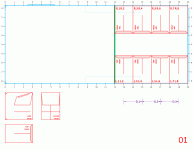
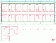
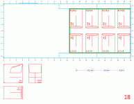
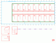
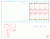
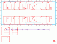
I'm not sure if I understood this correctly, I'm sure you don't mean turn top cabinets 90-degrees and face them completely down, because that would block a good part of the mouth, also then they would fire straight down at the floor and create major reflections, so maybe an inverted-V up by the roof? I sketched a few pictures here with different mouth-direction combinations to look at and consider... viewing the trailer from behind...Another possible "trailer tunnel" configuration would be cabinets on either side facing in, 36" direction fore and aft, with cabinets on top facing down. An alignment strip of wood (or some type of interlocking foot/receiver arrangement) would be needed to keep the top cabinets from "dancing" and partially toppling into the tunnel during operation, but it would be fairly little work to tip half the cabinets to either side, leaving about an 18" aisle down the center for gear storage.
Attachments
here are first 10 different arrangement to review for consideration...
Attachments
-
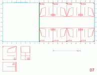 (007)2x4.gif38.4 KB · Views: 26
 -
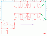 (008)2x4+ext.gif40.9 KB · Views: 30
 -
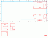 (009)4x4.gif29.9 KB · Views: 29
 -
 (010)4x4+ext.gif31.7 KB · Views: 27
 -
 (006)2x4+ext.gif41.5 KB · Views: 28
 -
 (005)2x4.gif39.2 KB · Views: 22
 -
 (004)2x4+ext.gif35.2 KB · Views: 24
 -
 (003)2x4.gif32.4 KB · Views: 23
 -
 (002)2x4+ext.gif33.8 KB · Views: 33
 -
 (001)2x4.gif30.7 KB · Views: 32
here are second 10 different arrangement to review for consideration...
Attachments
-
 (017)1x8.gif41.4 KB · Views: 27
 -
 (018)2x4.gif31.8 KB · Views: 25
 -
 (019)1x8.gif39.7 KB · Views: 24
 -
 (020)2x4.gif30.5 KB · Views: 25
 -
 (016)1x8.gif42.8 KB · Views: 28
 -
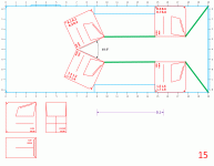 (015)4x4+v+ext-3.gif38.9 KB · Views: 26
 -
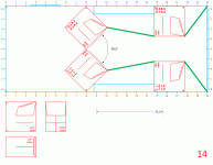 (014)4x4+v+ext-2.gif37.8 KB · Views: 32
 -
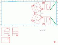 (013)4x4+v+ext.gif38.8 KB · Views: 22
 -
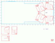 (012)4x4+v.gif35.3 KB · Views: 33
 -
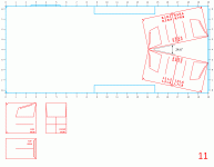 (011)4x4-v.gif36.4 KB · Views: 28
That's exactly what I meant, but thought the trailer interior width was 90", and the cabinets were 36" deep. There will be "major reflections" in any of the configurations.I'm not sure if I understood this correctly, I'm sure you don't mean turn top cabinets 90-degrees and face them completely down, because that would block a good part of the mouth, also then they would fire straight down at the floor and create major reflections, so maybe an inverted-V up by the roof? I sketched a few pictures here with different mouth-direction combinations to look at and consider... viewing the trailer from behind...
For practical reasons #2 or #8 look like the most viable arrangements. As previously stated, the "V" sections at the exit end are probably not needed, but the top of the tunnel should be capped in either configuration.
Last edited:
- As far as flipping cabinets on top pointing downward, it was a good idea, but I can't find a practical application for it, it's easy enough to throw some plywood on top, I am tabling that idea for the time being, can be discussed later. Unless there is a physics-related reason to point top cabs downward that way.
- I understand that the "extenders" shown in green are not going to change much acoustically at low frequencies. The lines are mainly there to show the "hypothetical" horn sides. And maybe my tops can go into that area splayed inwards and firing crisscross.
- Question 1 - is there a reason to end the array with a flat "end cap" - compared to a 90-degree V at the back end of the tunnel? Such a V would couple and "begin" the movement of soundwaves through the tunnel. The rest of the tunnel delayed accordingly.
- Question 2 - is there a reason to keep an identical spacing between delay zones? I realize that the delay would have to be adjusted if the distance changes. But would having different delay zones increase cancelations across a spectrum of frequencies? Wonder if it would make the sound better or worse in the end? As in more cancelations or more summation.
- I played around and came up with a few variations of arrays #14 and #16. They are attached to this message. I will post my opinion of what I like and dislike about each numbered array in the next day or two (and I welcome any other opinions as always).
Attachments
-
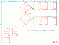 (016-5)2x2+2x2-v.gif40.2 KB · Views: 22
 -
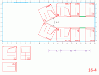 (016-4)2x2+2x2.gif41.8 KB · Views: 22
 -
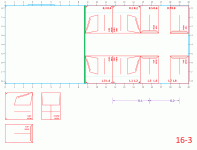 (016-3)2x2+2x2.gif35.4 KB · Views: 17
 -
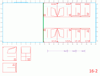 (016-2)2x2+2x2.gif35.6 KB · Views: 22
 -
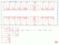 (016)1x8.gif42.8 KB · Views: 19
 -
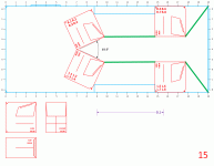 (015)4x4+v+ext-3.gif38.9 KB · Views: 19
 -
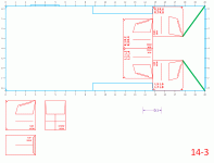 (014-3)4x4-90.gif32.3 KB · Views: 33
 -
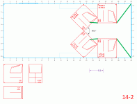 (014-2)4x4+v+ext.gif36.7 KB · Views: 31
 -
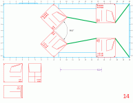 (014)4x4+v+ext-2.gif37.8 KB · Views: 32
 -
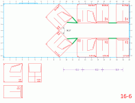 (016-6)2x2+2x2-v.gif40.4 KB · Views: 23
Tops splayed inward is a bad idea if they are covering an area wider than the trailer, as it will result in severe comb filtering (peaks and dips) other than at the apex point about 6 -10 feet from the rear of the trailer.The lines are mainly there to show the "hypothetical" horn sides. And maybe my tops can go into that area splayed inwards and firing crisscross.
- Question 1 - is there a reason to end the array with a flat "end cap" - compared to a 90-degree V at the back end of the tunnel? Such a V would couple and "begin" the movement of soundwaves through the tunnel. The rest of the tunnel delayed accordingly.
- Question 2 - is there a reason to keep an identical spacing between delay zones? I realize that the delay would have to be adjusted if the distance changes. But would having different delay zones increase cancelations across a spectrum of frequencies? Wonder if it would make the sound better or worse in the end? As in more cancelations or more summation.
1) The sound waves "begin" in the throat of the horn. The horns all pointing in appears to have better symmetry, but I'd encourage comparing either configuration.
2) I think in a closed tunnel, a shorter tunnel length will have less problems than a longer tunnel, but I'd encourage comparing either configuration. I can easily predict that none of the closed tunnel configurations will sound as good or be as loud as two wide vertical array, but without testing can't easily predict which configuration will sound the worst. although I can state that the reduction in tunnel volume in configuration 14 & 16-5 will result in more problems than the rest.
Once you start compromising proper set ups for reduced labor, you are just looking for the most favorable exchange rate.
Art
- Status
- This old topic is closed. If you want to reopen this topic, contact a moderator using the "Report Post" button.
- Home
- Loudspeakers
- Subwoofers
- The Ultimate Boombox...
