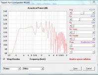
Hi, I have modeled a tapped horn in hornresp and this is what hornresp predicts with 2,83 volt.

Here with one watt applied and it totally screws up the response. So what model can I rely on. I would like to know when I hit xmax.

Parameters is this. Hope someone can help.

Thanks in advance Sebastian
Here with one watt applied and it totally screws up the response. So what model can I rely on. I would like to know when I hit xmax.
Parameters is this. Hope someone can help.
Thanks in advance Sebastian
Sebastian,Hi, I have modeled a tapped horn in hornresp and this is what hornresp predicts with 2,83 volt.
View attachment 494657
Here with one watt applied and it totally screws up the response. So what model can I rely on. I would like to know when I hit xmax.
View attachment 494656
Parameters is this. Hope someone can help.
View attachment 494660
Thanks in advance Sebastian
Speakers respond to voltage. Voltage in to the speaker impedance, which varies with frequency results in in the bizarre and useless watt curve.
To figure at what voltage the speaker hits Xmax simply advance voltage a bit at a time until Xmax is reached. To figure how many watts that takes, take voltage squared and divide by the impedance, for example 20V x 20V =400/4 ohms =100 watts.

You are saying the speaker is 60 ohm at some frequency, and yes 23 volts into 60 Ohms would only be 8.8 watts at that frequency. You can look at the Hornresp impedance curve and compare it to the excursion and frequency response to get the full picture.Hi weltersys, do you mean like this. Grey line is with 23v and impedance has raised to 60 ohm = 8,8watt.
I am usually concerned with the minimum impedance, which also usually happens to be at the minimum excursion. A voice coil that has little movement does not dissipate heat as well, so there is more likely hood of burnout at the frequency of minimum impedance.
ok, I´m hitting xmax on 5 mm with 23 volt,

at spl like this

but what are the impedance, I read more than 60 ohm at 43 hz.

Sorry but I am a bit confused. Can I really only give it less than 10 watt before I hit xmax or can I feed it with say 23x23/8 omh = 66 watt.
at spl like this
but what are the impedance, I read more than 60 ohm at 43 hz.
Sorry but I am a bit confused. Can I really only give it less than 10 watt before I hit xmax or can I feed it with say 23x23/8 omh = 66 watt.
Attachments
Hi Sebastian,
Typical fixed width construction is parabolic expansion, you can go into the Con labeled fields and press the [p] key to switch to parabolic simulation.
thanxs neodan, but I don´t see any alteration in frequence response when shifting.
1) Looks like about 5 ohms at 28Hz, at the excursion minima, 23 volts delivers about 106 watts there.1)ok, I´m hitting xmax on 5 mm with 23 volt, at spl like this
2)but what are the impedance, I read more than 60 ohm at 43 hz.
3)Sorry but I am a bit confused. Can I really only give it less than 10 watt before I hit xmax or can I feed it with say 23x23/8 omh = 66 watt.
2) The impedance varies with frequency, the average is generally about the equivalent of the nominal impedance, an 8 ohm speaker (usually) averages around 8 ohms. The impedance minima will generally be very close to the speaker's DCR. That said, some amplifiers are very sensitive to the minimum impedance, and may perform poorly if the impedance goes too low at any frequency.
3) The speaker draws power from the amp depending on how much voltage is produced in to the impedance at any particular frequency. You don't "give" a speaker watts, you give it voltage, the speaker "takes" as many watts as the impedance determines at a particular frequency.
Hornresp also shows impedance peaks as narrower and higher than will be seen in actual measurements. At any rate, don't worry about the impedance peaks, worry about the impedance minima, where the speaker will be drawing the most power (measured in watts) from the amp.
My thoughts:
1. Convert segments from CON to PAR as previously suggested
2. Include "cone compensation" in the sim. If you don't, you're going to see a bigger dip in the upper frequency response than expected. For a 15" driver, this is probably going to be around 4.5L. Just up Vtc to 4.5L and set Atc to Sd (855 cm^2)
3. The layout looks pretty complex for what you're trying to achieve. A simple expansion S=470, S4=1200 achieves a similar response with a much simpler layout to convert to an actual build.
4. This driver doesn't look like it wants to do 30 Hz. More like 40 Hz. Set S1=250, S4=1680, L23 to 231 and S2 and S3 auto and you'll see what I mean. The result is actually not a bad response curve at all for a single-expansion TH. I've got a spreadsheet that can be used to give you a layout for that type of build.
My thoughts:
1. Convert segments from CON to PAR as previously suggested
2. Include "cone compensation" in the sim. If you don't, you're going to see a bigger dip in the upper frequency response than expected. For a 15" driver, this is probably going to be around 4.5L. Just up Vtc to 4.5L and set Atc to Sd (855 cm^2)
3. The layout looks pretty complex for what you're trying to achieve. A simple expansion S=470, S4=1200 achieves a similar response with a much simpler layout to convert to an actual build.
4. This driver doesn't look like it wants to do 30 Hz. More like 40 Hz. Set S1=250, S4=1680, L23 to 231 and S2 and S3 auto and you'll see what I mean. The result is actually not a bad response curve at all for a single-expansion TH. I've got a spreadsheet that can be used to give you a layout for that type of build.
Thanx for the tips. How do you set s2 and s3 to auto?
Uppe FR does not change with Vtc and Atc altered, but that is not important since i´m cutting off at about 60 hz.
I have 2 FL horns one with 15" corner loaded 45 degrees into wallcorner. The other front firering with 18" driver, more that 1200 liter volume and 200+ kg. But I have 2 x 15" spare drivers and would like to mount TH on the ceiling over the listening position, just to give more viceral impact and extra grunt
1. "Tools.. Loudspeaker Wizard"
2. Under "Schematic", where is says "Manual" on the right hand side, double-click to change it to "Auto". Do this for both S2 and S3.
- Status
- This old topic is closed. If you want to reopen this topic, contact a moderator using the "Report Post" button.
- Home
- Loudspeakers
- Subwoofers
- Tapped horn question