Tapped Horn: usually twice the size of a vented box, but will put out ~6dB more across the same frequency range. Increased distortion when doing the extra SPL, though, since there's a lot of pressure acting on the cone. Quarter-wave resonator, so again, group delay isn't as good as that of a sealed box. Can't be used below tuning. Great when you have limited budget, but lots of space - you can get a lot of noise out of inexpensive drivers.
THs are higher-order alignments than vented systems, which means that for the same box volume, you should be able to achieve a lower F3 at the same SPL than with a vented alignment, but you may have to use a different driver to get it.
Stories of boxes needing to be nearly twice as large (actually box size depends on what compromises you choose re passband efficiency and low frequency output, but that's a whole other story) are usually based around someone trying to use the same driver in a vented alignment or a TH.
Maybe we should start a discussion on what makes the perfect TH driver
") .
.As for distortion, I'd like to see distortion tests done at the same output level to see if that suggestion that THs suffer from higher distortion really has merit. Measuring at the same voltage from the amp does not have that much value as it's the alignment's SPL capability in its passband that counts. There's also the issue of if that increase in distortion, if it does exist at the same SPL level as other alignments, is actually audible. Basically the question is if there's a difference, and if the difference really makes a difference
.Frankly, I'd be more concerned about the out of band peaks that are characteristic of most THs, particularly if they're close to the passband. To me, this, and their limited usable bandwidth, are the main issues with them.
Karlson's 1951 design vs a reflex the size of its rear chamber
An externally hosted image should be here but it was not working when we last tested it.
As for distortion, I'd like to see distortion tests done at the same output level to see if that suggestion that THs suffer from higher distortion really has merit. Measuring at the same voltage from the amp does not have that much value as it's the alignment's SPL capability in its passband that counts. There's also the issue of if that increase in distortion, if it does exist at the same SPL level as other alignments, is actually audible. Basically the question is if there's a difference, and if the difference really makes a difference
I believe Art has done some, measuring distortion of a ported vs TH cabinet for a 18SW115. The TH was capable of ~6dB more output, but was a bigger box and produced more distortion when doing the extra 6dB.
Chris
I believe Art has done some, measuring distortion of a ported vs TH cabinet for a 18SW115. The TH was capable of ~6dB more output, but was a bigger box and produced more distortion when doing the extra 6dB.
Chris
Yup, that's why I was clear that I think the distortion level should be checked at the SAME dB output, not the same voltage drive. IOW, for Art's example, back off the output by 6dB, then measure the distortion then.
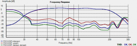
It's been theorized that "extra pressure" on the driver's cone increases the distortion. See attached example, which shows measured distortion for my DSP-corrected POC3 at different drive levels (ignore the labels, I forgot to change them, LOL). At the highest level was just below where the amp's limiter started to kick in. The PA310 driver used in the POC3 has a fairly soft cone. Note what the curve looks like, and consider that the excursion minima for the design, the points at which the greatest pressure is being applied to the cone, occur at 39 Hz and 95 Hz. I suspect the bump @ 80 Hz at the highest level was a measurement artifact (the ground on which the TH was placed for these measurements was gravel, and therefore may have contributed to the distortion at very high levels if the TH's bottom panel was flexing significantly). Since then I've done a few minor adjustments to POC3 to correct panel flex at the mouth, including a metal brace across the bottom of the panel.
Attachments
Very interesting (and brave) to post these curves. Not sure I know how to read 'em. Could the test conditions be described more fully please. Smoothing?
The distortion is around minus 15-20db or 10-15%?
It would also be interesting to see the distortion when the speakers and amps are not being pushed toooo hard.
Ben
The distortion is around minus 15-20db or 10-15%?
It would also be interesting to see the distortion when the speakers and amps are not being pushed toooo hard.
Ben
Very interesting (and brave) to post these curves. Not sure I know how to read 'em. Could the test conditions be described more fully please. Smoothing?
The distortion is around minus 15-20db or 10-15%?
It would also be interesting to see the distortion when the speakers and amps are not being pushed toooo hard.
Ben
Sure - the measurement was performed outdoors, Dayton UMM6 mike, iNuke 3000DSP providing the power, mike placed 25 feet from the TH's mouth (the limit of my cabling). The iNuke's DSP is being used to smooth the TH's response between 40 Hz and 200 Hz, and if you know what to look for you can see signs of this in the distortion curve
. 48dB/oct filters are applied above and below this passband. The FR curve was smoothed using HolmImpulse's default settings. The test signal was a 10 second sine sweep, done at various levels, the last one one just below when the amp's limiter light started to flicker. At this point distortion is around 15~20dB as you mentioned. Note: HornResp predicts in-band excursion maximum to occur just above 50 Hz. I performed the test to determine how linear the TH's response is as voltage level is increased. The distortion measurement was a bit of an afterthought, and I was really just looking for any gross distortion caused by the driver exceeding Xmax. I didn't even bother to measure the voltage levels - I just chose three that represented three very different power levels and let HolmImpulse normalize the measurement. As you can see, the TH's response remains very linear across the passband, as the FR curves at the three different voltage levels indicated in the graph remain practically the same.
Next time I have a chance to do the measurement (should be fairly soon - there's another build awaiting testing!), I'm going to rest the TH on a hard flat surface, to minimize any additional distortion being added because of an improper surface for testing. I'll also be adding some bracing inside POC's mouth, which I hope will address the bump in distortion between 70 to 100 Hz. And I plan to do some further optimization of the DSP "correction".
- Status
- This old topic is closed. If you want to reopen this topic, contact a moderator using the "Report Post" button.