Hi,
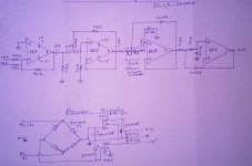
I have build a low pass filter for a sub-woofer as attached circuit. The filter circuit is worked. But there is a issue with frequency controller in the circuit. When i turn the frequency controller clock wise, it makes deep base, but sound level get very very low. when i turn the frequency controller anti-clock wise, it makes mid base, but sound level get too high.
So i feel the frequency controller is control the volume level of the audio signal rather than controlling the frequency level. Can you anyone check the circuit and assist me to over come this issue improving the design?
Attachments
When i turn the frequency controller clock wise, it makes deep base, but sound level get very very low. when i turn
the frequency controller anti-clock wise, it makes mid base, but sound level get too high.
This has three series filters (one high pass and two low pass). You might be better off with a more
straightforward circuit, with one fixed second order low pass filter, or two fixed ones in series for fourth order.
A 10k level control could be at the output.
Last edited:
This has three series filters (one high pass and two low pass). You might be better off with a more
straightforward circuit, with one fixed second order low pass filter, or two fixed ones in series for fourth order.
A 10k level control could be at the output.
Hi,
Do you mean bass will be better if the high pass filter is removed from the circuit? I think the 1st low pass filter near 50K volume controller is act as a 2nd order low pass filter.
Can you pls give me a better circuit (2nd order or 4th order low pass filter) if you have?
Hi,
With music it will inevitably get louder the higher the setting.
You need some form of overall level control.
rgds, sreten.
Hi,
Can you pls explain more?
Hi,
Do you mean bass will be better if the high pass filter is removed from the circuit? I think the 1st low pass filter
near 50K volume controller is act as a 2nd order low pass filter.
Can you pls give me a better circuit (2nd order or 4th order low pass filter) if you have?
Yes, the bass will be better without the high pass filter, unless you have a subsonic problem with your turntable, etc.
If you want a second order filter, delete the high pass, and also delete the low pass with the pot. Add a 10k pot at the main output.
If you want a fourth order filter, delete the high pass, and use resistors in the first filter instead of the pot. Add a 10k pot at the main output.
You'll have to recalculate the filter R and C values to get the cutoff that you want.
Hi,
Can you pls explain more?
Hi,
It will simply get louder as you up the x/o frequency,
if your using normal music programme to test.
You need to add some form of gain control.
rgds, sreten.
Yes, the bass will be better without the high pass filter, unless you have a subsonic problem with your turntable, etc.
If you want a second order filter, delete the high pass, and also delete the low pass with the pot. Add a 10k pot at the main output.
If you want a fourth order filter, delete the high pass, and use resistors in the first filter instead of the pot. Add a 10k pot at the main output.
You'll have to recalculate the filter R and C values to get the cutoff that you want.
Hi Rayma,
Got you. But, actually i'm not a expert in this area. I just made filter circuit referring the sketch. So i need you all kind help to get nicer and loud bass to my sub-woofer system doing some improvement to the low pass filter circuit since currently it doesn't. I have TDA8954 class D amplifier to power subs with this filter circuit. As i explain at the beginning of the forum, sound level get too low when the 50k pot is turned clock wise. There is no louder sound though i turn all the volume controllers up in the amp to it's maximum. But when the 50k pot is turned anti clock wise, the sound level get too way loud with mid frequencies and there is very high excursion on the subs too. So i have to turn down the amplifier volume. But the issue is this stage is lack of bass and rich of mid.
As you explain, i can remove high pass which has been place at the beginning of the circuit. there are two 0.1u capacitors and two 56k resistors. it is OK if i removes this RC network and connect pin 1 of IC 1 to Pin 3 of IC 3? There is another filter network with 1u and 7.5k resistor. Do i need to remove this too?
What would be happened if i change 50k pot to 10k pot and change 0.1u two capacitors in the 1st low pass network to 0.22u? I used web page named Sallen-Key Low-pass Filter Design Tool to select RC value and kept cut off frequency as 40Hz.
Pls note that there is a 50k pot at end of the filter circuit.
Last edited:
Hi,
It will simply get louder as you up the x/o frequency,
if your using normal music programme to test.
You need to add some form of gain control.
rgds, sreten.
Hi Sreten,
Actually i'm not a expert in this area. I just made filter circuit referring the sketch. Can you pls show me how to add gain control to the system?
adjust the 56k in the summimg stage.
You have a gain of 56k/7.5k for each input. 7.5times+7.5times
i.e. 200mVac at both L & R inputs gives 3Vac after the summing stage.
add a 100k lin law variable resistor parallel to the 56k (or change that to 120k).
When the 100kVR is max gain is (56k||100k) / (7.5k||7.5k) = -9.6times
at half rotation the gain changes to (56k||50k) / (7.5k||7.5k) = -7times
at 9/10ths rotation the gain changes to (56k||10k) / (7.5k||7.5k) = -2.3times
adjust the 56k in the summimg stage.
You have a gain of 56k/7.5k for each input. 7.5times+7.5times
i.e. 200mVac at both L & R inputs gives 3Vac after the summing stage.
add a 100k lin law variable resistor parallel to the 56k (or change that to 120k).
When the 100kVR is max gain is (56k||100k) / (7.5k||7.5k) = -9.6times
at half rotation the gain changes to (56k||50k) / (7.5k||7.5k) = -7times
at 9/10ths rotation the gain changes to (56k||10k) / (7.5k||7.5k) = -2.3times
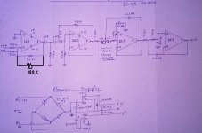
Hi AndrewT,
Noted your feedback. Hope this will help to improve volume level of the filter circuit. I have sketched the design as you mentioned. Can you check the attached img and let me know if the drawing is OK as you suggested?
In addition to this, can you pls let me know if you have any advice to improvement to the rest of circuit to get loud and deep base to my subs?
Attachments
 Moved to subwoofer forum
- Status
- This old topic is closed. If you want to reopen this topic, contact a moderator using the "Report Post" button.
- Home
- Loudspeakers
- Subwoofers
- Low Pass filter circuit for sub-woofer - Design error