Hello all.
Back in the late '70s, early '80s I used to manufacture a lot of knock-off professional sound reinforcement cabinets under the brand name MetroSound, for a wholesaler here in Chattanooga Tennessee.
I was also a mobile DJ, providing coordination and entertainment for many of the larger parties and dances in the area.
We tested all the commercially available cabinets at the time, and I was not able to find anything acceptable for sub-bass that I could simply copy, so I elected to design and build my own. After about two years of studying every book on the subject that I could find, I built two prototypes by simply modifying some old 2'x3'x4' boxes that I already had on hand as as leftovers from an earlier experiment.
My goal was to have decent response down to 20hz, with full efficiency at 30. Even after all I had read and all the calculations I had made, I was still more or less shooting in the dark, and therefore not expecting much the first time around.
What I'd managed to settle on was a 4x12" driver, direct radiator, with a back loaded folded horn below. After we had gotten these boxes together, we loaded them with some cheap Radio Shack drivers having a resonance somewhere around 20hz, and began our testing.
Well, the results just blew me and my partner away. We had pant-leg shaking sound that you could really feel... far below what you could actually hear. I had intended to build four of these (to achieve the right mouth size) if they worked okay, and load them with decent drivers, but these worked so well, that they were more than enough for our purposes at the time, so we just stopped there.
On a regular basis, girls would come up to the console complaining that there was too much bass, causing their heart to stop beating, inability to breathe, dizziness, etc... Of course we thought that was great fun, and cranked it up even louder...")
Anyway, I'm thinking of building another system which will be about four times larger than the one I was using then. I'm thinking about simply copying my original design. However, I'm also now wondering, if I really did get that lucky back then, or was I just easily impressed because of the fact that there really wasn't anything like that around, for me to actually compare with.
So (finally), my question to you all, is: If I will go to the trouble to rip one of these apart to take the measurements, then draw and model the whole thing in 3D cad... would some of you be kind enough to run the computer simulations, and provide your opinions on the real efficiency of this design, as compared to others that are available today?
One thing I can state for certain. These have a healthy chest punch to them, and a full, smooth sound that I like much better than my CV EL-36s.
Thanks.
Back in the late '70s, early '80s I used to manufacture a lot of knock-off professional sound reinforcement cabinets under the brand name MetroSound, for a wholesaler here in Chattanooga Tennessee.
I was also a mobile DJ, providing coordination and entertainment for many of the larger parties and dances in the area.
We tested all the commercially available cabinets at the time, and I was not able to find anything acceptable for sub-bass that I could simply copy, so I elected to design and build my own. After about two years of studying every book on the subject that I could find, I built two prototypes by simply modifying some old 2'x3'x4' boxes that I already had on hand as as leftovers from an earlier experiment.
My goal was to have decent response down to 20hz, with full efficiency at 30. Even after all I had read and all the calculations I had made, I was still more or less shooting in the dark, and therefore not expecting much the first time around.
What I'd managed to settle on was a 4x12" driver, direct radiator, with a back loaded folded horn below. After we had gotten these boxes together, we loaded them with some cheap Radio Shack drivers having a resonance somewhere around 20hz, and began our testing.
Well, the results just blew me and my partner away. We had pant-leg shaking sound that you could really feel... far below what you could actually hear. I had intended to build four of these (to achieve the right mouth size) if they worked okay, and load them with decent drivers, but these worked so well, that they were more than enough for our purposes at the time, so we just stopped there.
On a regular basis, girls would come up to the console complaining that there was too much bass, causing their heart to stop beating, inability to breathe, dizziness, etc... Of course we thought that was great fun, and cranked it up even louder...
Anyway, I'm thinking of building another system which will be about four times larger than the one I was using then. I'm thinking about simply copying my original design. However, I'm also now wondering, if I really did get that lucky back then, or was I just easily impressed because of the fact that there really wasn't anything like that around, for me to actually compare with.
So (finally), my question to you all, is: If I will go to the trouble to rip one of these apart to take the measurements, then draw and model the whole thing in 3D cad... would some of you be kind enough to run the computer simulations, and provide your opinions on the real efficiency of this design, as compared to others that are available today?
One thing I can state for certain. These have a healthy chest punch to them, and a full, smooth sound that I like much better than my CV EL-36s.
Thanks.
4x12" sub boxes, driver type and T/S parameters?
Hi there DM: We will need the driver type and T/S parameters as well as dimensions for the box and its internal configuration to enter in Horn Response program. There should be several Diyaudio here persons who will run a simulation. regards, Michael
Hi there DM: We will need the driver type and T/S parameters as well as dimensions for the box and its internal configuration to enter in Horn Response program. There should be several Diyaudio here persons who will run a simulation. regards, Michael
We would load them with state of the art drivers that we could run in the sims anyway. I would not be too stuck on having to use the old drivers. We will find something equivalent of probably much better given how much technology has improved.
We need drawings with dimensions of key parts - namely cross sectional distance at key points where the areas change or at vertices of corners. The length between the changes in cross sectional area. The volume or enough dimensions of the back chamber to estimate the volume.
We need drawings with dimensions of key parts - namely cross sectional distance at key points where the areas change or at vertices of corners. The length between the changes in cross sectional area. The volume or enough dimensions of the back chamber to estimate the volume.
Thanks guys.
I already know what parameters are needed. (remember, I designed these originally) I just didn't feel that I was really qualified to run the simulations, being relatively unfamilliar with the software. I also have no desire to run the inferior RS drivers, and I figured you folks might have some good suggestions in that area, when the time comes.
Mainly just checking to see if anyone was interested in helping. And now that I see that you are, I'll be back with the drawings just as soon as I can get that accomplished.
Thanks again.
Hello again guys.
The first generation horn that I originally spoke about in this thread, was a very good performer ...at least according to my memory.
There was however, a second generation, a sequel, if you will, that we built afterward as the basis for our "mega-system". These were designed to be utilized in groups of at least four per channel. But depending on the size of the show, we could group as many as sixteen when setting two channels up on a stage, as there were thirty two bins, in all.
Obviously, these horns would make a LOT of noise, but I was disappointed overall by their fidelity. The bass didn't go as low as I expected ...they lacked punch ...and they sounded just a little vague, or "boomy" to my ears. I eventually rented the whole system out for a couple of years to a local nightclub, and I had to add twelve 4560 JBL horns, loaded with LF EV drivers, to get the punch and clarity back that I was looking for in that installation.
In my opinion, it was the drivers that we used in these cabinets that were the main problem. See, I ordered thirty two drivers, and they didn't come in until just before a big show I had scheduled. Unfortunately they also came in spec'd wrong. Guitar speakers with a free air resonance of probably 200hz. ...not really what you'd want in a subwoofer driver, but I had a show to do, so I went ahead and installed them.
I happened to have one of these boxes sitting around here with the side already cut out, so I drew these up first, (rather crudely) to give you-all an opportunity to see the basic design, until I can get a chance to do the others.
If you'd like to run some simulations on these, I'd be very interested in the outcome, as to my thinking, this should be a slightly superior design in theory, as compared to the original.
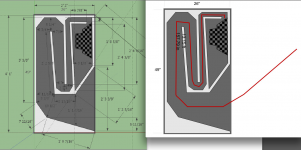
I have changed only one thing when copying these horns to the drawing. There is a floor in the actual driver enclosure, where the flat face of the cabinet ends. I'm not sure why I originally included that feature, but bear in mind that it reduced the volume of the area of the compartment surrounding the rear of the driver, by probably around a cubic foot.
There are no angles included in the this drawing's dimensions ...mainly because I was not able to figure out how to get Sketchup to print them on the drawing. If you absolutely need them, I will find some other way of getting them documented for you. The internal width of the cabinet is not shown, but the material is all 5/8" thick, and the width across the inside is 16-3/4". Also note that the floor these rest on, actually forms part of the horn mouth. According to my earlier calculations, that gives another 2-1/2' - 3' feet of effective horn length.
Here are the drawings:
https://www.flickr.com/photos/122644358@N03/sets/72157652290896090
The first generation horn that I originally spoke about in this thread, was a very good performer ...at least according to my memory.
There was however, a second generation, a sequel, if you will, that we built afterward as the basis for our "mega-system". These were designed to be utilized in groups of at least four per channel. But depending on the size of the show, we could group as many as sixteen when setting two channels up on a stage, as there were thirty two bins, in all.
Obviously, these horns would make a LOT of noise, but I was disappointed overall by their fidelity. The bass didn't go as low as I expected ...they lacked punch ...and they sounded just a little vague, or "boomy" to my ears. I eventually rented the whole system out for a couple of years to a local nightclub, and I had to add twelve 4560 JBL horns, loaded with LF EV drivers, to get the punch and clarity back that I was looking for in that installation.
In my opinion, it was the drivers that we used in these cabinets that were the main problem. See, I ordered thirty two drivers, and they didn't come in until just before a big show I had scheduled. Unfortunately they also came in spec'd wrong. Guitar speakers with a free air resonance of probably 200hz. ...not really what you'd want in a subwoofer driver, but I had a show to do, so I went ahead and installed them.
I happened to have one of these boxes sitting around here with the side already cut out, so I drew these up first, (rather crudely) to give you-all an opportunity to see the basic design, until I can get a chance to do the others.
If you'd like to run some simulations on these, I'd be very interested in the outcome, as to my thinking, this should be a slightly superior design in theory, as compared to the original.
I have changed only one thing when copying these horns to the drawing. There is a floor in the actual driver enclosure, where the flat face of the cabinet ends. I'm not sure why I originally included that feature, but bear in mind that it reduced the volume of the area of the compartment surrounding the rear of the driver, by probably around a cubic foot.
There are no angles included in the this drawing's dimensions ...mainly because I was not able to figure out how to get Sketchup to print them on the drawing. If you absolutely need them, I will find some other way of getting them documented for you. The internal width of the cabinet is not shown, but the material is all 5/8" thick, and the width across the inside is 16-3/4". Also note that the floor these rest on, actually forms part of the horn mouth. According to my earlier calculations, that gives another 2-1/2' - 3' feet of effective horn length.
Here are the drawings:
https://www.flickr.com/photos/122644358@N03/sets/72157652290896090
DemoMan,Obviously, these horns would make a LOT of noise, but I was disappointed overall by their fidelity. The bass didn't go as low as I expected ...they lacked punch ...and they sounded just a little vague, or "boomy" to my ears.
I have changed only one thing when copying these horns to the drawing. There is a floor in the actual driver enclosure, where the flat face of the cabinet ends. I'm not sure why I originally included that feature, but bear in mind that it reduced the volume of the area of the compartment surrounding the rear of the driver, by probably around a cubic foot.
The internal width of the cabinet is not shown, but the material is all 5/8" thick, and the width across the inside is 16-3/4". Also note that the floor these rest on, actually forms part of the horn mouth. According to my earlier calculations, that gives another 2-1/2' - 3' feet of effective horn length.
Looks like a long version of what is commonly called a "Scoop" design, which fits in the continuum of TQWP and TH designs. Reducing the back chamber puts the design more in TH territory, and would create an acoustical band pass.
Usually there is a phase cancellation somewhere in the upper passband of these designs, which does kill "punch", subjectively "punch" is in the 60-160Hz range.
In multiples, the horn would be extended as your red line shows, but even singly the path length of around 10 feet is 1/4 wavelength of 28.5 Hz, very low for "back in the day", a JBL 4530 scoop is only about half that length.
Art
Attachments
Last edited:
Yes, I'm well familiar with the "scoops". They were very much in vogue in the late '70s, early '80s, and we used to ship them out by the truckload. I never cared for them myself though. I always felt that the sound was much too "boomy". I have two new unpainted single 18s still sitting in the warehouse from back in the day, if anyone's interested. One day people just stopped buying them, and after that you couldn't give them away.
Regarding the design's similarity to a TH: I, nor anyone else I knew at the time, had ever heard of such an animal. However I vaguely recollect that the objective I had in mind, was a sort of horn loaded acoustical labyrinth.
BTW, at the risk of appearing too ignorant; ...what is a "TQWP"?
Regarding the design's similarity to a TH: I, nor anyone else I knew at the time, had ever heard of such an animal. However I vaguely recollect that the objective I had in mind, was a sort of horn loaded acoustical labyrinth.
BTW, at the risk of appearing too ignorant; ...what is a "TQWP"?
Ah yes, I see.
Art is right, in that when I designed these I didn't stick to any standard model, but ventured out with a sort of seat of the pants, educated guess, hybrid. The original 4x12" worked very well, but it may have had an additional fold in the horn, I just can't remember.
These should have performed well also, I believe. But who could tell, with those guitar speakers in there..? I think that if there's a flaw in the design, it would be the back chamber volume tuning. I do like the way these look. You put four of them together, and the resulting 4'x6' horn is pretty intimidating.
DemoMan,Regarding the design's similarity to a TH: I, nor anyone else I knew at the time, had ever heard of such an animal. However I vaguely recollect that the objective I had in mind, was a sort of horn loaded acoustical labyrinth.
Back in 1962, the type of horn you built was patented as a "tuned acoustical device", R.G.Pruden's box had the advantage of accommodating different driver parameters. It also shared similarities to the "acoustical labyrinth", though back then most acoustical labyrinth designs were fairly small.
Art
Attachments
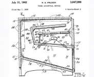
Lol... Now that is different! And no... I don't think it is very much like mine, other than the folded tuned port.
Did you see how that thing works..? It appears to have a heavy solid sprung diaphragm between the driver and the horn/port. No way that any high frequencies are coming out of the mouth above the resonance of the port/plate combo... I'd think the transient response of the port would be miserable though.
That's interesting, I've never seen that done before.
Okay... had another look. I see how it works now. The horn throat inlet is adjustable to (as you say) accommodate different driver parameters.
Still though... in comparison to mine, the horn rate is shorter, more conical and aggressive. Also the diver is located physically within the horn mouth, and therefore able to resonate the port from either end. I'd say it's closer to a real TH, than to my design.
And yes, it does (intentionally) hold similarities to the acoustical labyrinth.
Last edited:
Hi Y'all,
Should be easy to simulate in Hornresp.
Yes. I'm anxious to see what the numbers reveal about these. I had high hopes when I built them.
DemoMan,Lol... Now that is different! And no... I don't think it is very much like mine, other than the folded tuned port.
It appears to have a heavy solid sprung diaphragm between the driver and the horn/port.
The spring/bolt wingnut assembly simply adjusts the back chamber volume. Other than the minor variation in speaker placement, R.G.Pruden's box is functionally identical to your design.
Art
As I related in #13, I understand how the hinged throatplate works, after enlarging the diagram and having a second look. Now I haven't actually seen the patent (as you have), but to my mind, adjusting the horn inlet size would have a more profound effect on the performance of the unit, than adjusting the chamber volume by the same amount of plate movement. One thing is for certain; with that design you can't effect one without altering the other.The spring/bolt wingnut assembly simply adjusts the back chamber volume. Other than the minor variation in speaker placement, R.G.Pruden's box is functionally identical to your design.
About the driver location: I don't see that as a '"minor" variation'.
Some minor variations can have a major effect at certain frequencies, but little at others.To my mind, adjusting the horn inlet size would have a more profound effect on the performance of the unit, than adjusting the chamber volume by the same amount of plate movement. One thing is for certain; with that design you can't effect one without altering the other.
About the driver location: I don't see that as a '"minor" variation'.
The cool thing about simulation programs like Hornresp or Akabak is you can individually make adjustments on chamber volume, horn inlet size, driver location, and driver TS parameters and determine the effect each has on frequency response, and figure out what optimizes the range you are most concerned with.
Yes, I am well aware, and that's exactly what I'm wanting to see here.The cool thing about simulation programs like Hornresp or Akabak is you can individually make adjustments on chamber volume, horn inlet size, driver location, and driver TS parameters and determine the effect each has on frequency response, and figure out what optimizes the range you are most concerned with.
I have those programs myself. In fact I have had them for a long time. I just have not used them enough to feel comfortable with the results.
Speaker building is as much an art, as a science. With these sort of calculations, one needs real world experience gained from comparing the finished physical item with the theoretical one. I have never had the opportunity since I acquired these softwares to actually do this, so I don't trust the (hypothetical) results I derive from the software.
Hopefully someone(s) here does have that kind of acquired wisdom, and will eventually take on the chore of simulation.
- Status
- This old topic is closed. If you want to reopen this topic, contact a moderator using the "Report Post" button.
- Home
- Loudspeakers
- Subwoofers
- MetroSound Professional Hornloaded Subwoofer Designs