Does the model break down for larger inductances....
Hi Ben,
Hornresp has no problems simulating drivers with high inductance voice coils, provided that the value of inductance remains constant with frequency. What Hornresp cannot do is to accurately simulate a driver having a voice coil inductance that varies with frequency.
(Hornresp also assumes that the voice coil resistance remains constant with frequency, except when the Power Compression tool is used).
Kind regards,
David
Now that's a definitive answer from McBean!Hi Ben,
Hornresp has no problems simulating drivers with high inductance voice coils, provided that the value of inductance remains constant with frequency. What Hornresp cannot do is to accurately simulate a driver having a voice coil inductance that varies with frequency.
(Hornresp also assumes that the voice coil resistance remains constant with frequency, except when the Power Compression tool is used).
Kind regards,
David
So the answer is that the Thiele-Small model starts to depart from accurately simulating a loudspeaker when inductance*, resistance, (and I suppose all other parameters) vary with frequency. The T-S model can't handle such instances. Is it because the underlying theory of electrical analogies to mechanical parameters has no analogy?
That's OK with me. The T-S model (or a sim of the model) is good enough to provide useful guidance although not perfect enough to be an object of veneration as some seem to hold it.
Ben
*How can that be? Where else does the inductance of something vary, except for saturation or similar instances?
Last edited:
This is very, very wrong!Is it because the underlying theory of electrical analogies to mechanical parameters has no analogy?
It is very interesting that there are differences.
But in practical applications box placement is one of the greater factors. Room shape and dimensions are even a greater factors in the system sound.
Inductance varries first of all with frequency of the incoming signal.
But the actual operating circumstances are a wee bit more complicated. Move a coil of wire in a magnetic field and you generate a voltage. It is constantly happening as speakers operate. They generate electricity. A voltage that is unwanted but present.
It lags in time, a little bit. Phase is used to measure the differential in time.
Add to the soup the saturation of the center pole of the speakers motor. That is easier to do when you have a high efficiency driver. As motor efficiency is linked to the strength of the magnetic field that is focused between the pole and the top plate of the driver.
This to can change factors concerning with the generation side (back EMF) and the drive side of sending power to the driver.
Little wonder that many intelligent men and women have chased the math describing these effects for a generation.
And sadly in the low frequency end of design it makes little difference.
When modelling crossovers it is quite a bit more important. Especially in the human voice range.
Hi Bach On,
Post #650: "... Some have suggested I wouldn't need any damping material. Since this is your design, what do you think?"
I think you are doing the right thing in using at least a little open pore foam glued to the inside. It would not hurt to place a layer of fiberglass batting into the bottom. "Some" are correct, if you are looking only at the performance of a subwoofer.
Post #650: "...change my order to the 2 ohm version of the HT18. I can connect the dual voice coils in parallel and come up with a 4 ohm circuit..."
From the SI website:
"- HT18 Dual 2 ohm voice coils
Re 3.5 ohms"
That means to me, that they have both coils in series for their T/S specification (if they are "Dual 2 ohm"), and that they are Re=1.75 Ohm ea. , also, if you connect them in parallel you have to divide 1.75 by 2, and get Re=0.875 Ohm. It's easy to get parallel and series mixed up. I'm withholding what I think about their documentation. From what I hear their product is OK.
Good to hear that you are making progress.
Gotta run.
Regards,
I should have said series, rather than parallel.
I used poly-fill batting for the hypotenuse board. Sprayed adhesive on it then spread it out. Also put some in the area where the speaker will be positioned. I did put fiberglass at the bottom in that void beside the horizontal portion of the port.
Would putting anything actually within the port help with any issues of "noise"? I have more fiberglass and poly-fill.
I've been able to round over the exit of the port a bit. But I'm still working on it. It won't be perfect.
Had to go buy more wood. But I haven't put on the outside supports for the hypotenuse board. Hope to do that early this week.
I did write Stereo Integrity requesting that the driver order be changed. But they've shut down operations to get to some projects according to their Facebook page. So I don't know if they will do anything in the near future.
Bach On
Last edited:
A little show and tell on the triangular bass cabinet:
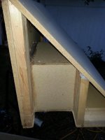
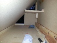
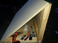
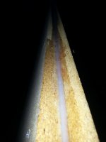
I'll post some pics of the interior with the stuffing PDQ. Gotta go play at church.
BTW - here's a picture of the organ console:

The things above the keyboards are the tabs. This is the part that is being fabricated right now. There will be more tabs, so the items on the left and right have to be moved. The yellow lines are indicating where the relocation will be made. This is a whole lot of the cost of this project.
Bach On


I'll post some pics of the interior with the stuffing PDQ. Gotta go play at church.
BTW - here's a picture of the organ console:

The things above the keyboards are the tabs. This is the part that is being fabricated right now. There will be more tabs, so the items on the left and right have to be moved. The yellow lines are indicating where the relocation will be made. This is a whole lot of the cost of this project.
Bach On
It is very interesting that there are differences.
But in practical applications box placement is one of the greater factors. Room shape and dimensions are even a greater factors in the system sound.
Yes, placement and room issues are tremendously huge factors.
But not when you measure outside, or use the speakers outside.
Besides, this type of simulators are not really for simulating placement (beyond boundary conditions) or room effects (beyond .frd of the measured room response and/or making a guess based on leakage).
What these simulators ARE supposed to do, and do very well, is estimate the performance of a speaker in a relatively open area with the inclusion of a (or a few) infinite boundaries.
There are VERY few cases where simulators like Hornresp are not able to do that very accurately. This type of ultra high excursion driver is one of these cases. More on this in a minute.
When I'm wrong I admit it. When searching for the UM18 measurements on data-bass I saw the familiar "inductance hump", which shouldn't be there in such a low inductance driver. This means I may be wrong about inductance being the sole cause of the issue. The cause may just be very large and heavy voice coils, although at this point I don't want to speculate too much. However hopefully I can be excused for correlating this effect with inductance, since 99 percent of this type of ultra high excursion driver with very large and heavy voice coils also has ultra high inductance.
Anyway, the method still works on this type of driver. It works great to sim the UM18 with it's "inductance hump" too, even though it's not a high inductance driver and the hump doesn't look like it's caused by inductance (since measure Le:Re ratio is so low).
Anyway, the correction method works great, but it's back to the drawing board to find the exact cause of the issue that makes this type of driver not sim right, which is useful in identifying them without seeing them measured first, which is one of the biggest advantages to the correction method. If Le:Re is higher than 1:1 you can bet it won't sim right, but now there are a couple of identified drivers with Le:Re much lower than that, that also need correction.
Last edited:
Moving forward.A little show and tell on the triangular bass cabinet:
I'll post some pics of the interior with the stuffing PDQ.
Bach On
The advice you've been getting about stuffing seems related only to people eyeballing the hypothetical speaker output sim for maximum loudness at some points. And at that, only related to the fraction of sound coming via the port. There's more to speaker building than that.
Some of us would stuff the whole darn thing in the interest of better sound. Having a tuned box inside the pipe loft may be musically undesirable; I can't say for sure.
Your box is tuned to a single "note" and something of a crap-shoot exactly what that note will turn out to be. I think I'd stuff more suppression into the box and not sweat whatever minor loss at some limited range of frequencies that will entail.
But having tuned organ pipes (which are obviously carefully tuned to musical values!!!) is quite another matter.
Ben
Last edited:
Hi Bach On,
Post #665: "Would putting anything actually within the port help with any issues of "noise"? I have more fiberglass and poly-fill."
Don't place any absorpive material inside the port, or close to its inlet. It would not help with noise, and it will reduce the desired port action. If you overstuff the box, or stuff the port you do not have a bass reflex enclosure any more. You will loose all of the low end SPL gain resulting from the Helmholtz resonator effect. The rounding of the port edges does not have to be perfect or pretty. I have chamfered edges inside of cabinets with a wood rasp, and close as I can tell that works just fine. Knock off any loose fibers, e.g.: w/ some coarse sandpaper stapled to a wooden block. Looks like you're making good progress on building the box.
Post #665: "I did write Stereo Integrity requesting that the driver order be changed. But they've shut down operations to get to some projects according to their Facebook page. So I don't know if they will do anything in the near future."
Looks like SI has at least a communications problem. Maybe time to switch to a more reliable supplier. I have never had any problems with Parts Express, and the UM18-22 looks like a better driver to me.
Thanks for the pictures, and keep 'em comin', that adds a lot more reality to the thread.
Regards,
Moving forward.
The advice you've been getting about stuffing seems related only to people eyeballing the hypothetical speaker output sim for maximum loudness at some points. And at that, only related to the fraction of sound coming via the port. There's more to speaker building than that.
Some of us would stuff the whole darn thing in the interest of better sound. Having a tuned box inside the pipe loft may be musically undesirable; I can't say for sure.
Your box is tuned to a single "note" and something of a crap-shoot exactly what that note will turn out to be. I think I'd stuff more suppression into the box and not sweat whatever minor loss at some limited range of frequencies that will entail.
But having tuned organ pipes (which are obviously carefully tuned to musical values!!!) is quite another matter.
Ben
AND... you are right back to your leaky sealed recommendation. Stuffing the whole box will completely kill the port resonance, and this is a recommendation that goes completely against what the OP asked for - more output at 16 hz. Your recommendations are bizarre in that they are always exactly the opposite of what the OP has requested. Sure, if OP doesn't like it he can stuff it later, but recommending 100 percent stuffing of a ported box that was ported for a reason is crazy. This is a PA application.
OMG Ben, tuning is not a crap shoot. Not at all. Even in the most complex horns sim/fold/measurements, tuning is always within about 2 hz of simulated estimate. Putting it in room (especially in a corner) can change things a bit, but the port resonance is pretty wide bandwidth so it doesn't matter that much.
Tuned organ pipes are not quite another matter, tuning a resonator (of any type) is quite simple and exactly the same principles are involved.
I havn't EVER used ANY stuffing in ALL the bass cabs i've built over the years. It's NOT needed @ those frequencies. You often see stuffing advised for TL subs etc, but it should be something effective like Long Haired Wool. Even then it only really helps to tame the upper harmonics !
Plus unless the stuffing is restrained, it will move more & more in sympathy with increasing airflow, which affects the T/S parameters = there goes your sim !
Plus unless the stuffing is restrained, it will move more & more in sympathy with increasing airflow, which affects the T/S parameters = there goes your sim !
I havn't EVER used ANY stuffing in ALL the bass cabs i've built over the years. It's NOT needed @ those frequencies.
Funny, all these years I've taken it as a universal truth that whenever you have two parallel walls, you've got a problem.
Do you have any non-averaged spectrums of the sound to post? Other data? Or are you basing your opinion on listening experience?
Ben
Funny, all these years I've taken it as a universal truth that whenever you have two parallel walls, you've got a problem.
At some frequency yes, although that frequency is usually well above the bandwidth of a sub. A bit of stuffing or lining is always good in fullrange speakers or very large or long subs (large or long enough to produce resonances in or near the passband) but often it's not a problem for "regular" (smallish) subs crossed fairly low as they usually are.
But this is where sims (or at least a bit of math) come in really handy to let you know beforehand what's likely to be problematic and what's not.
I'll throw my experience into the ring.
I can't post the measurements as they are proprietary.
But a while back I did a fair bit of comparative work with subwoofers padded and unpadded.
For subwoofers only. As in a box designed to operate lower than 200 hertz it makes precious little difference. As in none. No measureable difference and no audible difference when compared blind.
The thickness of the absorber has to be 1/4 wavelength of the frequency you want to absorb. For 128 hertz that is 2 feet thick. For 64 hertz that is 4 feet thick and for 32 hertz that is 8 feet thick. Now there are ways to cheat that a little but not much more. You can add active layers that flap in the correct breeze and you get a suck out at the tuned frequency. Those are the real life bass traps. And they are not small or simple installations.
If you want my two cents it would be to try the subwoofer without any absorbant. If you feel that there is some need for it you have a few large holes to access the enclosure with.
As for parallel walls there will be a box resonance along the longest dimensions. But quick modeling tells me that it will probably help fill in the low end a little more than be a complete detriment.
I've mentioned the wood pipes that are plugging up the opening from the speaker chamber into the pipe chamber.
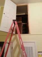
Here's the doorway into the speaker chamber from the nursery.
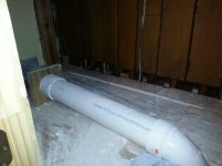
This shows the floor right behind the wood pipes. (This photo was before we put any of the speakers in the chamber) The PVC pipe comes from the blower and goes into the windchest that maintains the air pressure. I've built an area with concrete blocks and 2x4s to get the speakers over this pipe. You can see the large wood Bourdon pipes on the right. Notice how close they are to one another. This is the opening into the pipe chamber. These pipes will be removed and taken away when the sound engine is installed.
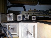
I stuck my camera out an opening above the Bourdon pipes. I pointed it down at the floor of the pipe chamber. You can see that there are more pipes in front of these.
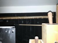
Here's a shot of the shades in the pipe chamber. The shades will control the volume that passes into the Sanctuary.
Bach On
Here's the doorway into the speaker chamber from the nursery.

This shows the floor right behind the wood pipes. (This photo was before we put any of the speakers in the chamber) The PVC pipe comes from the blower and goes into the windchest that maintains the air pressure. I've built an area with concrete blocks and 2x4s to get the speakers over this pipe. You can see the large wood Bourdon pipes on the right. Notice how close they are to one another. This is the opening into the pipe chamber. These pipes will be removed and taken away when the sound engine is installed.

I stuck my camera out an opening above the Bourdon pipes. I pointed it down at the floor of the pipe chamber. You can see that there are more pipes in front of these.

Here's a shot of the shades in the pipe chamber. The shades will control the volume that passes into the Sanctuary.

Bach On
Last edited:
Respectfully, Mark's opinion differs from that of two other authorities, Rod Elliot ("ESP") and Bill CollisonI'll throw my experience into the ring.
I can't post the measurements as they are proprietary.
But a while back I did a fair bit of comparative work with subwoofers padded and unpadded.
For subwoofers only. As in a box designed to operate lower than 200 hertz it makes precious little difference. As in none. No measureable difference and no audible difference when compared blind.
Damping Treatments
The attached chart is from Collison showing greatly improved response with damping.
Without a whole lot of probably unfeasible stuffing, there is no realistic way to mangle the basic Helmholtz frequency. Too bad. So doing much about the main boom down there is not in play. So no quibbling with Mark about the absence of much audible or measurable influence on the basic box note.
The question then is the audibility of resonances in (1) a tall box, (2) considering that drivers play distortion harmonics that are vastly more audible than their fundamentals, and (3) we're only guessing what frequencies will be pumped into the new box (again, with upper notes creeping in from a low-slope crossover or an undocumented organ synthesizer being a lot more audible).
In light of that, I'd suppose the improvement shown in the graphic is quite applicable here.
Ben
Attachments
Last edited:
Originally Posted by bentoronto
Funny, all these years I've taken it as a universal truth that whenever you have two parallel walls, you've got a problem.
It can't be sorted by stuffing in subs.
Do you have any non-averaged spectrums of the sound to post? Other data? Or are you basing your opinion on listening experience?
1 - Richard Small "Loudspeakers in vented boxes" is where i discovered that stuffing affects the T/S parameters & therefore response. Any extra moving mass is the culprit.
2 - I was going to show TL stuffing responses, but your Collo link is fine.
mwmkravchenko is in agreement with me. Also Collo's link states & shows similar.
Full-range speakers have acoustic wool stuffed into the box to remove energy due to friction as the air moves through the fibres. The effectiveness of this approach diminishes as frequency is reduced. By the time we get below 300hz, the stuffing is basically useless.
For subwoofers, stuffing will not help with the fundamental resonances, however it is still useful for treating harmonics, which may be exicted by distortion from over-driving, or by shallow rolloff slopes in your bass management system.
Damping Treatments
With designs for sub duty, ie less than 100Hz, & this is for 16Hz, stuffing will only make things worse !
In light of that, I'd suppose the improvement shown in the graphic is quite applicable here.
Ben
No it's not. The graphic shows a HUGE resonance (15 db variation in the dip and peak) at a VERY low frequency (100 hz). A good bit of stuffing (like a LOT) in the right part of the box absolutely will help that, as the picture shows.
BUT in the sims I did, OP's box has a VERY benign resonance MUCH higher in frequency. IIRC it was maybe 2 or 3 db and up over 200 hz. I don't remember exactly and he didn't build from my sim anyway, he used tb46's. A resonance that small will be virtually inaudible, and if for some reason it is audible it probably won't be unpleasant. But if for some reason the OP doesn't like it, a small bit of stuffing would wipe it right out. Just keep the stuffing as far away from the port as possible (the complete opposite end of the box) and don't use more than necessary, it won't take much.
I do tl (and mltl) design too, these low frequency resonances are always present in those. They are easy to get rid of if you design them to be small in the first place and put the right amount of stuffing in the right part of the box. Easy stuff.
Last edited:
Hm, that's odd, my speakons have 1+ 1- 2+ 2-..they are really hard to see though, embossed on the tiny bit of plastic right next to the screw terminal...I haven't comitted them to memory yet, so I have to use a little pen flashlight to see them.
Sent from my SM-G920T using Tapatalk
Sent from my SM-G920T using Tapatalk
- Status
- Not open for further replies.
- Home
- Loudspeakers
- Subwoofers
- 16Hz for church organ
