Hi jphutchins,
Looks like you're having a good time w/ the model.
The background comes from a number of JBL/Infinity papers:
"Maximizing Performance from Loudspeaker Ports" by Salvatti, Devantier, Button
there seem to be 2 versions of this paper, one 4.5MB - http://koti.kapsi.fi/jahonen/Audio/Papers/AES_PortPaper.pdf - , and the other 861kB, and
AES 112th Convention, Munich, Germany:
"Vented=box geometry and low frequency reproduction: the aerodynamical approach" by Morkerken, Parzy, Pellerin, Polack, and
AES 116th Convention, Berlin, Germany:
"Sound source design in the very low frequency domain." by Pellerin, Polack, Morkerken.
You should be able to find these using Google. The last time I found them in JBL tech references.
As a general suggestion I would just make the center where it has a somewhat reduced port area (in my example the same as 2ea. 3"Dia. ducts), and then increase the throat and mouth areas until the velocity is below 15m/sec, or so. After that it's probably down to building and measuring. It may take some experimenting to come up w/ the optimum length for the slopes, lead-in and exit section, etc..
Regards,
Hi just a guy,
I have only used WinISD once or twice in the past, and for some reason I cannot get it to work on my current computer so I cannot do any further testing, but based on my recent investigations it seems that rather than specifying Eg directly, WinISD calculates the value of Eg internally based on the entered values for input power and Re.
If the same value of Eg is used in Hornresp as that calculated by WinISD, then the results will be the same.
The loudspeaker electrical input impedance (resistive and reactive components) varies with frequency as shown in the Hornresp electrical impedance magnitude chart - the impedance phase chart can be selected from the Tools menu. If Rg is zero then Eg and the complex impedance (not just the resistance) is used at each frequency to calculate the response curve. If Rg is not zero then the input voltage across the loudspeaker varies with frequency due to losses in Rg.
If Rg is zero then Hornresp uses the value of Eg and the impedance (not simply resistance) at each frequency to calculate particle velocity.
As far as I can gather without being able to check further, WinISD uses the power value specified by the user to calculate a value for Eg assuming that the load is Re. WinISD then uses that calculated constant value for Eg along with the frequency-dependent input impedance (not Re) the same way that Hornresp does, to calculate velocity.
WinISD calculates velocity correctly. It uses the value calculated for Eg together with the frequency-dependent input impedance, not Re.
Both calculate velocity correctly. When the same value is used for Eg, the results are the same. It's just that WinISD specifies power as the input, rather than voltage, which personally I find to be very confusing.
Specifying 240W as the input in WinISD is not the same as specifying Pmax = 240W in the Hornresp Maximum SPL tool.
In the first case, even though 240W is specified as the input power, it only applies when the load is a pure resistance equal to Re. It is the calculated value of Eg that is actually held constant across the frequency range, not the specified input power value.
In the second case, using the Maximum SPL tool in Hornresp holds the specified input power constant at 240W across the frequency range. It is the value of Eg that varies.
The reason for the large discrepancy initially was because in one case the voltage was held constant (in WinISD) and in the other case power was held constant (in Hornresp, by using the Maximum SPL tool). It was like comparing apples to oranges.
Kind regards,
David
The difference between 16 m/s (WinISD) and 76 m/s (Hornresp) for the same input parameters is a huge and shocking discrepancy.
I have only used WinISD once or twice in the past, and for some reason I cannot get it to work on my current computer so I cannot do any further testing, but based on my recent investigations it seems that rather than specifying Eg directly, WinISD calculates the value of Eg internally based on the entered values for input power and Re.
If the same value of Eg is used in Hornresp as that calculated by WinISD, then the results will be the same.
With a speaker and an amp in real life the resistance varies with frequency so I assume the simulators use Eg and the resistance at each frequency to calculate the frequency response curve. Correct?
The loudspeaker electrical input impedance (resistive and reactive components) varies with frequency as shown in the Hornresp electrical impedance magnitude chart - the impedance phase chart can be selected from the Tools menu. If Rg is zero then Eg and the complex impedance (not just the resistance) is used at each frequency to calculate the response curve. If Rg is not zero then the input voltage across the loudspeaker varies with frequency due to losses in Rg.
If that is correct, I assume Hornresp uses Eg and the resistance at each frequency to calculate the velocity too. Correct?
If Rg is zero then Hornresp uses the value of Eg and the impedance (not simply resistance) at each frequency to calculate particle velocity.
From what I understand from the quoted post, WinISD uses Eg and a constant Re to calculate velocity. Correct?
As far as I can gather without being able to check further, WinISD uses the power value specified by the user to calculate a value for Eg assuming that the load is Re. WinISD then uses that calculated constant value for Eg along with the frequency-dependent input impedance (not Re) the same way that Hornresp does, to calculate velocity.
This is the wrong way to calculate velocity since resistance is not constant at all frequencies. Correct?
WinISD calculates velocity correctly. It uses the value calculated for Eg together with the frequency-dependent input impedance, not Re.
So Hornresp calculates velocity correctly - what you see in the sim is what you would measure if you could actually measure velocity. And WinISD calculates velocity wrong - what you see in the sim is dramatically lower than you would measure if you could actually measure the velocity. Correct?
Both calculate velocity correctly. When the same value is used for Eg, the results are the same. It's just that WinISD specifies power as the input, rather than voltage, which personally I find to be very confusing.
Sorry for asking so many questions but I think a thorough understanding of this massive discrepancy is vital.
Specifying 240W as the input in WinISD is not the same as specifying Pmax = 240W in the Hornresp Maximum SPL tool.
In the first case, even though 240W is specified as the input power, it only applies when the load is a pure resistance equal to Re. It is the calculated value of Eg that is actually held constant across the frequency range, not the specified input power value.
In the second case, using the Maximum SPL tool in Hornresp holds the specified input power constant at 240W across the frequency range. It is the value of Eg that varies.
The reason for the large discrepancy initially was because in one case the voltage was held constant (in WinISD) and in the other case power was held constant (in Hornresp, by using the Maximum SPL tool). It was like comparing apples to oranges.
Kind regards,
David
Post #16
Hi jphutchins,
You are correct, raising the resonance even slightly by reducing the overall duct length brings the the upper frequency displacement down. You'll still have ample output @ 40Hz. I just bumped Eg to 60V, and the filtered displacement still stays below Xmax=8mm.
Your next limit is the power handling. Looking at the MCM 55-2421 I have my doubts as to the power rating in RMS, but it should do fine w/ music inputs. Without filters, and w/ Eg=60V you get an electrical input power of 133.36W @ 90Hz, and 197.98W @ 100Hz. By 130Hz Pin=389.27W so you need to keep you filter around 100Hz/4th order, and you would be good.
Regards,
Attachments
From the WinISD Help file
Make sure that both HR etc, & WinISD are set to show the same values, RMS or Peak or Peak to Peak, for comparison.
Port velocity
Port velocity is like cone excursion. Again, volume velocity through port is determined. Since we need port velocity, then, we just divide volume velocity by port area. This gives us RMS port velocity, which is optionally scaled, like cone excursion.
Air velocity - front/rear port
Air velocity graph shows how fast air mass travels in port. In order to keep chuffing noise low, you should limit the peak velocity at 5% of velocity of sound, or about 17 m/s. Like the cone excursion graph, the desired powerlevel is set also by same watts setting. Note that if air velocity peaks exceeds previously mentioned level. This graph can also be configured to show RMS, peak or peak-to-peak value. See the cone excursion graph explanation for RMS, peak and peak-to-peak values.
Make sure that both HR etc, & WinISD are set to show the same values, RMS or Peak or Peak to Peak, for comparison.
Hi Mr. Doom,
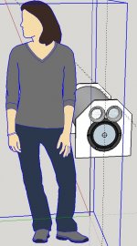
That sounds about right! I wonder though, if I'd like to put an 8" woofer at each end of one sonotube to balance it's weight (shoulder strap on each side carried like a duffle bag), then should the woofers be wired in opposite polarity from one another so that the cones are always moving in the same direction or as normal. Normal polarity meaning both woofers would compress the air in the box together then release together.
I also seem to be limited to something like this: https://www.madisoundspeakerstore.com/flares/ports/vents/4flare-complete-kit/ and I can only assume that they applied the results of the paper posted above by Oliver which suggests that a Normalized Flare Rate of 0.5 is generally the best. This paper also seems to suggest that I should just buy the ports since I cannot manufacture cylindrical ports, let alone flares, that are easier to model and simply work better.
Thanks,
J.P.
Edit: wiring both cones facing out in phase (as a normal dual driver BR) would work best.
Last edited:
Hi jphutchins,
Post #27: "...should the woofers be wired in opposite polarity from one another..."
They should be wired in phase, both cones moving out at the same time when tested w/ a small battery.
*******************************
A slot port would work just fine w/ the jet port principle. It's a bit different from just adding round-over ends to a duct.
You don't have to hit the exact perfect rate of transition inside the port. You have to look @ the wavelength v. the port dimensions, e.g. in case of a round duct 4"-6"Dia. versus a 1/4 wavelength of 33.86" for 100Hz. That could probably be glued together from cardboard tubes.
Regards,
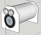
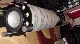
Sonotube 12" from home depot...
I was able to find some locals selling 18" sonotube...however, even with two woofers, I didn't figure how I could fit the port tube length required (wide enough to keep turbulence down) in such a squat design.
So Home Depot 12" tubes might work. Using 2x 15" long 3" ports with external flares from Precision Sound Products. Internal flare will likely be impossible. The external flare, in fact, must "stick out" past the woofer - mounting the 8" woofer will leave around 3" space for the two 3" tubes but nowhere near enough space for 2, or even 1, flare. Space for speakons on opposite end.
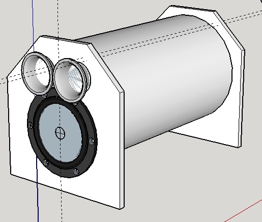

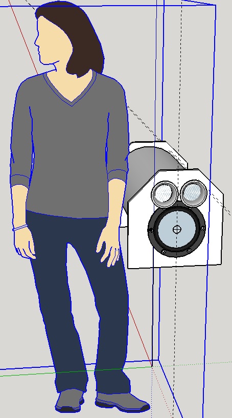
I'd like it to look more Dr Seuss, any ideas?
J.P.
I was able to find some locals selling 18" sonotube...however, even with two woofers, I didn't figure how I could fit the port tube length required (wide enough to keep turbulence down) in such a squat design.
So Home Depot 12" tubes might work. Using 2x 15" long 3" ports with external flares from Precision Sound Products. Internal flare will likely be impossible. The external flare, in fact, must "stick out" past the woofer - mounting the 8" woofer will leave around 3" space for the two 3" tubes but nowhere near enough space for 2, or even 1, flare. Space for speakons on opposite end.
I'd like it to look more Dr Seuss, any ideas?
J.P.
Attachments
 so you did the same sorta off center mount... looks like I'll have a rough time getting 2 3" ports in mine since in each design there is ca. 4" to spare and yours looks pretty tight.
Hi again,
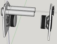
OK. Just as an example, you can make a folded duct for one of your lids, if you install the drivers as a PPSL (see: doodle_01). You got to make a lid this way or that way (and this one would be strong). I'll attach a very rough sketch of how that could be done, this one matches the dimensions of my last Hornresp example, 14"I.D. sono tube:
Regards,
Attachments
The 12" tube is definitely restrictive in execution ability. I don't think there's a way to put the 8" diver along with 2 3" ports into the tube. You could mount the 8 with the flange slightly outside the tube, so that only the back of the speaker is inside - this will give you maybe a 1/2" more room.
The 16" tube with the 12 and 2" ports is really pushing it. Have you modeled with 2" ports yet? tb46's ideas sounds pretty good - albeit a bit more difficult to execute depending on the size of the 8" drivers.
The 16" tube with the 12 and 2" ports is really pushing it. Have you modeled with 2" ports yet? tb46's ideas sounds pretty good - albeit a bit more difficult to execute depending on the size of the 8" drivers.
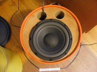
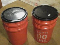
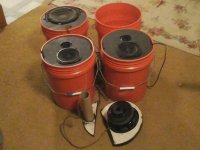
It is possible to fit two 1 7/8" ports and a 55-2421 on an 11 1/4" baffle in a very lightweight 20 liter bucket. I coned the bottom of the buckets like a champagne bottle to stiffen the bottom.
I built a couple of these and two mains in buckets that pack down to two buckets with the amp, battery and ipod inside.
Originally the sub had a double port, but I reduced it to one to split the baffle and make it pack better. For the couple of watts I use, port velocity isn't a problem.
Marc
I built a couple of these and two mains in buckets that pack down to two buckets with the amp, battery and ipod inside.
Originally the sub had a double port, but I reduced it to one to split the baffle and make it pack better. For the couple of watts I use, port velocity isn't a problem.
Marc
Attachments
Last edited:
You guys need to be a bit more adventurous with your sonotube designs. There's no need to try to shoehorn the vents onto the same face as the driver.
Hint: "SAS Bazooka"....")
Yeah - I didn't want to put that much more work into mine as my ports fit well enough. I guess you could do a 8" tube section for the port. The hardest part would probably be stiffening to keep it from collapsing by an accidental bump. Fiberglass reinforcement may be fun
Port Turbulence.
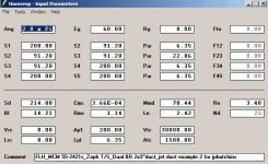
HornResp shows A-OK with 2x3" flared ports (Precision Ports). However, using such wide ports means I have to compromise and make the sonotube enclosure larger than is ideal.
So I modeled 2x2" flared ports from Precision Ports in HornResp (40.54cm2 flaring to 172.52cm2) - for mouth and throat particle velocity I get 16m/s at max power. Modifying the model to remove the flares gives an idea of particle velocity in the inside of the port - it is 60m/s. I cannot seem to find any literature clearly stating whether or not an extremely high particle velocity inside the port (not at the mouth or throat) will cause unacceptable compression or "chuffing".
Finally started cutting wood, just wanted to see if I can squeeze the design a hair more before I finalize.
Thanks for your help,
J.P.
- Status
- This old topic is closed. If you want to reopen this topic, contact a moderator using the "Report Post" button.
- Home
- Loudspeakers
- Subwoofers
- "Over the shoulder" vented box