Can my vintage amplifier power dual 8ohm subs?
Can a vintage Sansui AUD607G extra (90watts per channel) provide enough juice to power dual PASSIVE sub woofers with these specs?
Freq. Response: 50hz - 180hz
Input Sensitivity: 111mV
Power Handling 100 - 150 Watts
Impedance: 8 ohms
Not after super low 20hz low frequencies, just some decent 40 - 50 hz bass help for a speaker that rolls off around 100hz.
Will be using an active low pass filter to feed the amp's signal; planning to use the line aux in so the signal will pass through the amps preamp section.
I dont play loud. 80db would really be a stretch for me since I live in a small apartment and neighbours would kill me if I aim for concert levels.
Sansui specs:
Model Integrated DC amplifier
<Power amplifier section (Ground Floating, Super Feedforward & DD / DC method)>
Effective output 90W + 90W (8 ohms, 10 Hz ~ 20 kHz, THD 0.003%)
90W + 90W (8 ohms, 1 kHz, THD 0.002%)
Total harmonic distortion (10Hz ~ 20kHz, when effective output) 0.003% or less (8Ω)
Intermodulation distortion (60Hz: 7kHz = 4: 1, SMPTE) 0.003% or less (8Ω)
Output bandwidth (IHF, both ch behavior, THD 0.02%) 5Hz ~ 70kHz (8Ω)
Damping factor (new IHF, 20Hz ~ 20kHz) 100 (8Ω)
Frequency characteristic (1W) DC ~ 300kHz +0 -3dB
Envelope distortion Below measurable limit
TIM distortion (Sawtooth method) Below measurable limit
Slew rate ± 180V / μsec (8Ω)
Rise time 0.8μsec
<Equalizer amplifier part (Hi-Precision DC servo equalizer)>
Input sensitivity / input impedance (1kHz) Phono1,2 MM: 2.5 mV / 47kohm
Phono1,2 MC: 120MyuV / 3 ~ 40?
Tuner, Aux / DA, Tape / PCM Play1,2: 250mV / 27Keiomega
Phono maximum permissible input (1kHz, THD 0.01%) MM: 200mV
MC: 10 mV, TRANS system
Output level / impedance (1kHz) Tape rec (PIN): 250mV (47kΩ) / 600Ω
Total harmonic distortion (20Hz ~ 20kHz, at 5V output) Phono1,2 MM: 0.005% or less
Phono1,2 MC: TRANS system
RIAA deviation (MM, Rec out) 20Hz ~ 300kHz ± 0.2dB
SN ratio (A network) Short circuit Phono1,2 MM: 88dB or more
Phono1,2 MC: 79dB or more (120MyuV)
Tuner, Aux / DA, Tape / PCM Play1,2: 110dB or more
Phono input referred noise
(A network) Short circuit Phono1,2 MM: -140DBV
Phono1,2 MC: -157DBV
Channel separation (1kHz) Phono1,2 MM: 60dB or more
Phono1,2 MC: 50dB or more
Tuner, Aux / DA, Tape / PCM play: 80dB or more
Tone control Bass: ± 6 dB (50 Hz)
Treble: ± 6 dB (10 kHz)
Filter Low: 16Hz (-3dB, 6dB / oct)
Audio muting -20dB
<General>
Rated power consumption (Electrical Appliance and Material Control Law) 220W
External dimensions Width 460 × height 160 × depth 404mm
Weight 13.5kg
Thanks!
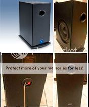
Here's a pic of the sub
Can a vintage Sansui AUD607G extra (90watts per channel) provide enough juice to power dual PASSIVE sub woofers with these specs?
Freq. Response: 50hz - 180hz
Input Sensitivity: 111mV
Power Handling 100 - 150 Watts
Impedance: 8 ohms
Not after super low 20hz low frequencies, just some decent 40 - 50 hz bass help for a speaker that rolls off around 100hz.
Will be using an active low pass filter to feed the amp's signal; planning to use the line aux in so the signal will pass through the amps preamp section.
I dont play loud. 80db would really be a stretch for me since I live in a small apartment and neighbours would kill me if I aim for concert levels.
Sansui specs:
Model Integrated DC amplifier
<Power amplifier section (Ground Floating, Super Feedforward & DD / DC method)>
Effective output 90W + 90W (8 ohms, 10 Hz ~ 20 kHz, THD 0.003%)
90W + 90W (8 ohms, 1 kHz, THD 0.002%)
Total harmonic distortion (10Hz ~ 20kHz, when effective output) 0.003% or less (8Ω)
Intermodulation distortion (60Hz: 7kHz = 4: 1, SMPTE) 0.003% or less (8Ω)
Output bandwidth (IHF, both ch behavior, THD 0.02%) 5Hz ~ 70kHz (8Ω)
Damping factor (new IHF, 20Hz ~ 20kHz) 100 (8Ω)
Frequency characteristic (1W) DC ~ 300kHz +0 -3dB
Envelope distortion Below measurable limit
TIM distortion (Sawtooth method) Below measurable limit
Slew rate ± 180V / μsec (8Ω)
Rise time 0.8μsec
<Equalizer amplifier part (Hi-Precision DC servo equalizer)>
Input sensitivity / input impedance (1kHz) Phono1,2 MM: 2.5 mV / 47kohm
Phono1,2 MC: 120MyuV / 3 ~ 40?
Tuner, Aux / DA, Tape / PCM Play1,2: 250mV / 27Keiomega
Phono maximum permissible input (1kHz, THD 0.01%) MM: 200mV
MC: 10 mV, TRANS system
Output level / impedance (1kHz) Tape rec (PIN): 250mV (47kΩ) / 600Ω
Total harmonic distortion (20Hz ~ 20kHz, at 5V output) Phono1,2 MM: 0.005% or less
Phono1,2 MC: TRANS system
RIAA deviation (MM, Rec out) 20Hz ~ 300kHz ± 0.2dB
SN ratio (A network) Short circuit Phono1,2 MM: 88dB or more
Phono1,2 MC: 79dB or more (120MyuV)
Tuner, Aux / DA, Tape / PCM Play1,2: 110dB or more
Phono input referred noise
(A network) Short circuit Phono1,2 MM: -140DBV
Phono1,2 MC: -157DBV
Channel separation (1kHz) Phono1,2 MM: 60dB or more
Phono1,2 MC: 50dB or more
Tuner, Aux / DA, Tape / PCM play: 80dB or more
Tone control Bass: ± 6 dB (50 Hz)
Treble: ± 6 dB (10 kHz)
Filter Low: 16Hz (-3dB, 6dB / oct)
Audio muting -20dB
<General>
Rated power consumption (Electrical Appliance and Material Control Law) 220W
External dimensions Width 460 × height 160 × depth 404mm
Weight 13.5kg

Thanks!
Here's a pic of the sub

Last edited:
I don't see any issue with LF.
But it is worth checking for input DC blocking capacitor.
BTW,
DC blocking capacitor in either the Source or the Receiver can reduce your low bass. Fitted to both then it can massively reduce your low bass.
Hmmm... Any chance an electronics idiot like me can identify that visually if I open up the chassis?
Or is there any other way for me to identify a blocking cap and know this?
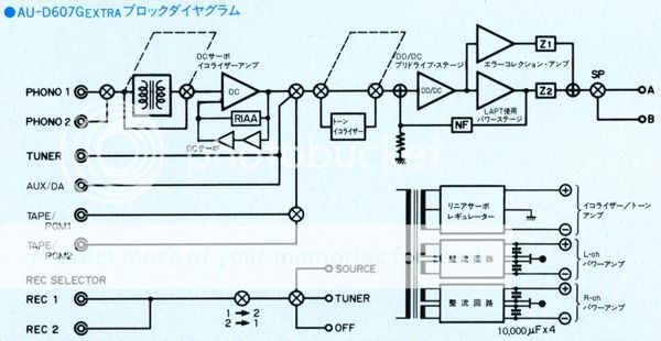
Here's the text from the literature of the Sansui translated from japanese using google's highly fail-worthy translation services.
Integrated amplifier that improvement has been subjected to, such as ground-floating circuit the AU-D607F Extra base. I is equipped with a ground-floating circuit of the new development. This circuit is one that has been developed from the review of the amplifier of the ground circuit, output amplifier, load (speaker), I am the power supply circuit to a complete closed loop. Furthermore, with the power supply unit to a floating power, to independent power transformer windings plus, minus, respectively, so that was a dual-bridge configuration to be rectified by the two sets of bridge, input in the ground circuit, output, interference of power I have to eliminate. This I am suppressing the harmful IHM distortion to very small in sound quality. The power supply unit I have adopted the left and right two independent power system. In addition, the electrolytic capacitor is adopted the newly developed high-linearity condenser of large capacity at low impedance. It is equipped with a linear step MC transformer in order to cope with MC cartridge. Furthermore, we allow for higher purity amplified by installed the optimal load is allowed to separate the load impedance for the MC cartridge for MM cartridge. The pre-drive stage of the power amplifier is equipped with a diamond differential circuit, the power stage is equipped with a super FF. This circuit has the same circuit configuration and the AU-D707G Extra. In addition, we are working to characteristic improvement by adopting a high-speed element NM-LAPT. The equalizer part has adopted the Hi-Precision equalizer, and we have achieved a wide range of RIAA deviation 20Hz ~ 300kHz ± 0.2dB. In addition, the power supply is adopted as the linear servo regulator, it has enabled a stable power supply a. The Subsonic filter I is equipped. DA, I am equipped with a PCM terminal. I have adopted the polarity display with power cord. Adopted the heat pipe and NM element has simple & straight signal path and the magnetic distortion measures is subjected. You can connect the two lines by twin relay speaker switch. recording selector and two types of source are independent, I is equipped with a 2 circuit tape monitor. There were two different colors of black and silver.
Will also attach a pic of the schematic on the OP.
Thanks A LOT!!!
Last edited:

The block diagram in post 1 does not show any coupling capacitors..............can identify that visually if I open up the chassis?
Or is there any other way for me to identify a blocking cap and know this?
..............
The coupling capacitors have three functions.
They couple audio signals from one module to the next.
They filter the frequencies that are allowed to pass.
They isolate (block) differences in DC voltage between modules.
Usually coupling capacitors in Solid State equipment are between 470nF and 10uF and more usually they are Electrolytic capacitors.
Looking inside they are between modules, or at the input, or at the output.
Between two modules you only need ONE coupling capacitor.
Nothing is gained by using two. Performance can be worse by using two.
You need to find out what is already fitted between the output of the Source and the input of the Receiver (that word again).
I buy amps second-hand or from the Salvation Army store - anything since 1980 that's within its original spec works fine and produces a fraction of the garbage that your speakers produce.
That's lots of watts for any usual domestric setting. Harmonic distortion from subs is a lot less important than in the middle range.
You can check the electric performance (freq and distortion and etc) of all your gear with REW and you don't need a mic. Buy a cable terminating in a pair of alligator clips and connect to the speaker terminals. EASY!!!!!
Ben
- Status
- This old topic is closed. If you want to reopen this topic, contact a moderator using the "Report Post" button.
- Home
- Loudspeakers
- Subwoofers
- Can my vintage receiver power dual 8ohm subs?