A member of the forum clued me in to a cardioid horn that Cerwin Vega patented a few years back.
I made a sim of it in Akabak.
If anyone's curious, here it is.
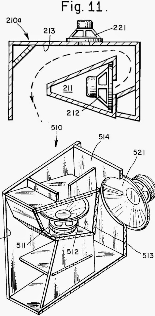
1) Here's the patent : Patent US6038326 - Loudspeaker and horn with an additional transducer - Google Patents
2) Here's some pics:
3) Here's some sims. I did these with a very small woofer, a Peerless 830970. That's a 2" driver, so obviously it's not going to play incredibly low. (I was curious to see if we could get cardioid response while maintaining high efficiency.)

Here's some thoughts on the design:
For the most part, this box is basically a way to combine a dipole woofer and a horn sub into a smaller footprint.
One way to look at the Cerwin Vega sub is that it's a variation on the cardioid sub featured on Kimmo Saunisto's page here: DIY Loudspeakers Kimmo Saunisto
Here's how this works:
The front wave and the rear wave of a dipole woofer cancel at low frequency.
The rear wave of a sealed box is isolated.
Combine the two, and you get a system that's not as efficient as sealed, more efficient than dipole, and has a forward lobe. (Because the forward lobe of the sealed combines with the forward lobe of the dipole.)
My choice of woofers is far from ideal. Basically I think that you want to use a much larger woofer for the dipole element in the horn. This is because we need equal output from the horn and the dipole. Due to the horn's efficiency advantage, we have to use a larger dipole woofer to compensate. You can see this phenomenon in Kimmo's projects, and in the patent pics of from Cerwin Vega.
I've built some Synergy horns that were cardioid, and the Unity horn patent is referenced by Cerwin Vega. So clearly there was some cross-pollinations there. I find the sound to be exceptional, even if the sims are unremarkable. To really make this project special I would use a miniDSP and separate amplifier channels so that the dipole response is equalized to match the horn's response, and then delay to increase the directivity.
I made a sim of it in Akabak.
If anyone's curious, here it is.
1) Here's the patent : Patent US6038326 - Loudspeaker and horn with an additional transducer - Google Patents
2) Here's some pics:
3) Here's some sims. I did these with a very small woofer, a Peerless 830970. That's a 2" driver, so obviously it's not going to play incredibly low. (I was curious to see if we could get cardioid response while maintaining high efficiency.)
Here's some thoughts on the design:
For the most part, this box is basically a way to combine a dipole woofer and a horn sub into a smaller footprint.
An externally hosted image should be here but it was not working when we last tested it.
One way to look at the Cerwin Vega sub is that it's a variation on the cardioid sub featured on Kimmo Saunisto's page here: DIY Loudspeakers Kimmo Saunisto
Here's how this works:
The front wave and the rear wave of a dipole woofer cancel at low frequency.
The rear wave of a sealed box is isolated.
Combine the two, and you get a system that's not as efficient as sealed, more efficient than dipole, and has a forward lobe. (Because the forward lobe of the sealed combines with the forward lobe of the dipole.)
My choice of woofers is far from ideal. Basically I think that you want to use a much larger woofer for the dipole element in the horn. This is because we need equal output from the horn and the dipole. Due to the horn's efficiency advantage, we have to use a larger dipole woofer to compensate. You can see this phenomenon in Kimmo's projects, and in the patent pics of from Cerwin Vega.
I've built some Synergy horns that were cardioid, and the Unity horn patent is referenced by Cerwin Vega. So clearly there was some cross-pollinations there. I find the sound to be exceptional, even if the sims are unremarkable. To really make this project special I would use a miniDSP and separate amplifier channels so that the dipole response is equalized to match the horn's response, and then delay to increase the directivity.

Here's my Akabak script. It's based on a hornresp export, I simply added an additional radiator and 1-2 dipole woofers.
System 'S1'
|DATA EXPORTED FROM HORNRESP - RESONANCES NOT MASKED
|COMMENT: 830970 FLH
|~~~~~~~~~~~~~~~~~~~~~~~~~~~~~~~~~~~~~~~~~~~~~~~~~~~~~~~~~~~~~~~~~~~~~~~~~~~~~~~~~~~~~~~~~~~~~~~~~~~~~~~~
|REQUIRED AKABAK SETTINGS:
|File > Preferences > Physical system constants:
|Sound velocity c = 344m/s
|Medium density rho = 1.205kg/m3
|Sum > Acoustic power:
|Frequency range = 10Hz to 20kHz
|Points = 533
|Input voltage = 2.83V rms
|Integration = 2Pi-sr
|Integration steps = 1 degree ... 1 degree
|Integration method = Cross
|~~~~~~~~~~~~~~~~~~~~~~~~~~~~~~~~~~~~~~~~~~~~~~~~~~~~~~~~~~~~~~~~~~~~~~~~~~~~~~~~~~~~~~~~~~~~~~~~~~~~~~~~
Def_Const |Hornresp Input Parameter Values
{
|Length, area and volume values converted to metres, square metres and cubic metres:
S1 = 5.00e-4; |Horn segment 1 throat area (sq m)
S2 = 20.00e-4; |Horn segment 1 mouth area and horn segment 2 throat area (sq m)
S3 = 80.00e-4; |Horn segment 2 mouth area and horn segment 3 throat area (sq m)
S4 = 320.00e-4; |Horn segment 3 mouth area and horn segment 4 throat area (sq m)
S5 = 1280.00e-4; |Horn segment 4 mouth area (sq m)
S99 = 13.90e-4; | set this to the SD of the dipole woofer
L12 = 16.00e-2; |Horn segment 1 axial length (m)
L23 = 16.00e-2; |Horn segment 2 axial length (m)
L34 = 16.00e-2; |Horn segment 3 axial length (m)
L45 = 16.00e-2; |Horn segment 4 axial length (m)
Vrc = 0.50e-3; |Rear chamber volume (cubic m)
Lrc = 7.62e-2; |Rear chamber average length (m)
|Parameter Conversions:
Sd = 13.90e-4; |Diaphragm area (sq m)
Arc = Vrc / Lrc;
}
|~~~~~~~~~~~~~~~~~~~~~~~~~~~~~~~~~~~~~~~~~~~~~~~~~~~~~~~~~~~~~~~~~~~~~~~~~~~~~~~~~~~~~~~~~~~~~~~~~~~~~~~~
|Network node numbers for this front-loaded horn system:
| 0-Voltage-1
| |
|4-Chamber-5-Driver-8-Segment-9-Segment-10-Segment-11-Segment-12-Radiator
|~~~~~~~~~~~~~~~~~~~~~~~~~~~~~~~~~~~~~~~~~~~~~~~~~~~~~~~~~~~~~~~~~~~~~~~~~~~~~~~~~~~~~~~~~~~~~~~~~~~~~~~~
Def_Driver 'sealed'
Sd=13.90cm2
Bl=2.82Tm
Cms=6.46E-04m/N
Rms=0.39Ns/m
fs=166.18Hz |Mmd = 1.39g not recognised by AkAbak, fs calculated and used instead
Le=0.10mH
Re=3.60ohm
ExpoLe=1
Def_Driver 'open'
Sd=13.90cm2
Bl=2.82Tm
Cms=6.46E-04m/N
Rms=0.39Ns/m
fs=166.18Hz |Mmd = 1.39g not recognised by AkAbak, fs calculated and used instead
Le=0.10mH
Re=3.60ohm
ExpoLe=1
System 'System'
Driver Def='sealed''Driver1'
Node=1=0=5=8
Driver Def='open' 'Driver2'
Node=1=0=11=13
| Driver Def='open' 'Driver3'
| Node=1=0=12=10
Duct 'Rear chamber'
Node=4=5
SD={Arc}
Len={Lrc}
Visc=0
Waveguide 'Horn segment 1'
Node=8=9
STh={S1}
SMo={S2}
Len={L12}
Conical
Waveguide 'Horn segment 2'
Node=9=10
STh={S2}
SMo={S3}
Len={L23}
Conical
Waveguide 'Horn segment 3'
Node=10=11
STh={S3}
SMo={S4}
Len={L34}
Conical
Waveguide 'Horn segment 4'
Node=11=12
STh={S4}
SMo={S5}
Len={L45}
Conical
Radiator 'Horn mouth'
Node=12
SD={S5}
Radiator 'Dipole Woofer'
Node=13
SD={S99}
Note that the null isn't perfect for positive wiring *or* negative wiring. Here's why:
With a dipole woofer and a sealed woofer, the two drivers are basically 180 degrees out of phase across the entire passband. With the Cerwin Vega, they're not. For instance, a 40hz horn has a pathlength of over two meters. Because the dipole woofer is both *inside* and *outside* the horn, the dipole woofer has one side that's a bit less than 90 degrees out-of-phase, and another side that's approximately 270 degrees out of phase.
On top of all that, the phase difference will depend on the dimensions of the enclosure!
So this is a surprisingly complex box.
As far as I can see, Cerwin Vega never sold anything like this. It was patented almost fifteen years ago. So one might argue that it was ahead of it's time.
Reverse the added driver so the magnet is in the horn, reverse the polarity (so that it adds in the horn mouth), delay the signal to the added driver. Use 21" Pyle for the added driver.
You need to give the radiators physical locations and angles in order to see if it produces a cardioid when you look at the polar plot. Add baffle width and height, turn on reflections/diffraction. Otherwise you are plotting response coming from assumed singular point in omni space.
This may be of interest for this topic: http://www.diyaudio.com/forums/subwoofers/258706-study-dipole-cardioid-bass-horn.html
This may be of interest for this topic: http://www.diyaudio.com/forums/subwoofers/258706-study-dipole-cardioid-bass-horn.html
You need to give the radiators physical locations and angles in order to see if it produces a cardioid when you look at the polar plot. Add baffle width and height, turn on reflections/diffraction. Otherwise you are plotting response coming from assumed singular point in omni space.
This may be of interest for this topic: http://www.diyaudio.com/forums/subwoofers/258706-study-dipole-cardioid-bass-horn.html
Oh cool, I didn't realize you could define the location of the radiator in space.
So you're saying that if I had a picture like this, that I could model the two radiators in Akabak, while including the gap between the two radiators and their size?
Updated script with physical locations of radiators
Yes. I have done it here below...
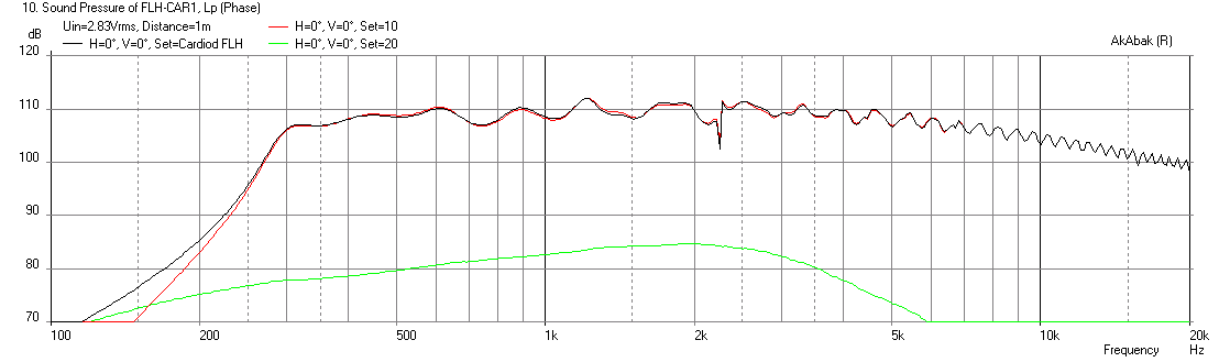
Here is the result of a script modified to include radiator locations and orientations. The horn loaded driver is very efficient and overpowers the dipole driver so not much cardiod action going on. You can see the output of dipole driver in red is 85dB and FLH one is 110dB. You will need a 100dB sensitive woofer for the dipole driver for it to make a difference in cardiod polars.
Freq Response (black=combined, red=horn mouth, green=rear dipole rad):
Polar (500Hz, 1kHz, 2kHz):

So you're saying that if I had a picture like this, that I could model the two radiators in Akabak, while including the gap between the two radiators and their size?
Yes. I have done it here below...
Here is the result of a script modified to include radiator locations and orientations. The horn loaded driver is very efficient and overpowers the dipole driver so not much cardiod action going on. You can see the output of dipole driver in red is 85dB and FLH one is 110dB. You will need a 100dB sensitive woofer for the dipole driver for it to make a difference in cardiod polars.
Freq Response (black=combined, red=horn mouth, green=rear dipole rad):
Polar (500Hz, 1kHz, 2kHz):
Code:
| Cardiod FLH mod of Patrick Bateman's script by xrk971 oct 21, 2014
| File FLH-CAR1

Def_Const |Hornresp Input Parameter Values
{

| *** add physical extent of speaker to place drivers and radiators relative ***
| Define external physical size of speaker and position of speaker relative to room for reflection and diffraction
Height=12.0 * 0.0254;       | Height of front baffle for in-room response inches
Depth=10.0 * 0.0254;        | Depth of speaker cabinet for in-room response inches
Width=6.0 *0.0254;          | Width in inches
Dist_wall=(5000 * 0.0254);   |Distance (inches) back of cabinet is away from back wall in inches
Speaker_pos=(5000 * 0.0254); | Position of radiator centerline above floor in inches

|Length, area and volume values converted to metres, square metres and cubic metres:

S1 = 5.00e-4; |Horn segment 1 throat area (sq m)
S2 = 20.00e-4; |Horn segment 1 mouth area and horn segment 2 throat area (sq m)
S3 = 80.00e-4; |Horn segment 2 mouth area and horn segment 3 throat area (sq m)
S4 = 320.00e-4; |Horn segment 3 mouth area and horn segment 4 throat area (sq m)
S5 = 1280.00e-4; |Horn segment 4 mouth area (sq m)

S99 = 13.90e-4; | set this to the SD of the dipole woofer

L12 = 16.00e-2; |Horn segment 1 axial length (m)
L23 = 16.00e-2; |Horn segment 2 axial length (m)
L34 = 16.00e-2; |Horn segment 3 axial length (m)
L45 = 16.00e-2; |Horn segment 4 axial length (m)

Vrc = 0.50e-3; |Rear chamber volume (cubic m)
Lrc = 7.62e-2; |Rear chamber average length (m)

|Parameter Conversions:

Sd = 13.90e-4; |Diaphragm area (sq m)

Arc = Vrc / Lrc;
}

Def_Driver '830970'  | Peerless 2in woofer
Sd=13.90cm2
Bl=2.82Tm
Cms=6.46E-04m/N
Rms=0.39Ns/m
fs=166.18Hz |Mmd = 1.39g not recognised by AkAbak, fs calculated and used instead
Le=0.10mH
Re=3.60ohm
ExpoLe=1

Def_Driver  '55-2421' | MCM 8 in, Qts 0.22, 8 mm xmax, 87dB
  SD=208.7cm2   |Piston
  fs=25.7Hz
  Mms=59.8g
  Qms=14.00
  Qes=0.22
  Re=3.4ohm
  Le=2.47mH
  Vas=30.4L

System 'Cardiod FLH'

| *** add room placement for reflections if desired ***
| Speaker with horn axis CL at Speaker_pos above floor and Dist_wall away from back wall
|OFF
Def_Reflector  HorizEdge
Bottom={Speaker_pos}  Top={Dist_wall+Depth}
AbsorbCoeff=0.2  | absorption of sound by nearby surfaces and walls
HAngle=0  VAngle=0


Driver Def='830970' 'Driver 1'   | Sealed back FLH driver, node=5 is driver face into horn, node=8 goes to rear chamber
Node=1=0=5=8


Driver Def='830970' 'Driver 2'  | Node=13 is back and radiating 180 deg out
Node=0=1=11=13                  | flip polarity of dipole driver

| *** rear sealed main chamber  ***
Enclosure  'Rear Chamber'  Node=8
Vb={Lrc*Arc}  Qb/fo=0.5  Lb={Lrc}  | set chamber Q to 0.50

Waveguide 'Horn segment 1'
Node=5=9  | changed to node 5 for front face of driver
STh={S1}
SMo={S2}
Len={L12}
Conical

Waveguide 'Horn segment 2'
Node=9=10
STh={S2}
SMo={S3}
Len={L23}
Conical

Waveguide 'Horn segment 3'
Node=10=11
STh={S3}
SMo={S4}
Len={L34}
Conical

Waveguide 'Horn segment 4'
Node=11=12
STh={S4}
SMo={S5}
Len={L45}
Conical

Radiator 'Horn Mouth'
Def='Horn Segment 4'
Node=12
x=0 y=0 z=0        |Mouth radiator position is reference as measurement centerline
HAngle=0 VAngle=0  | Rad is aimed horiz straight out for purposes of calculation diffractions and polars
WEdge={Width / 2}  | Diffraction width used is half width of cabinet
HEdge={Height/4}   | Diffraction width used is 1/4th of cabinet height
Reflection         | Turn on reflections
Label=10

Radiator 'Dipole Rad'
Def='Driver 2'
Node=13
x=0 y={+Height/2} z={-Depth}      | Dipole rad position is assumed on back side and offset up by half height
HAngle=180 VAngle=0  | Dipole Rad is aimed horiz back (180 deg) out for purposes of calculation diffractions and polars
WEdge={Width / 2}  | Diffraction width used is half width of cabinet
HEdge={Height/2}   | Diffraction width used is half of cabinet height
Reflection         | Turn on reflections
Label=20
Attachments


Last edited:
"The horn loaded driver is very efficient and overpowers the dipole driver so not much cardiod action going on. "
So, how much directivity are you assuming for the FLH portion of the horn?
Standing behind a small horn stack (4' x 4') shows a big difference in output, such that a big driver driven as I suggested above will achive a large degree of cancellation.
Can you write an AkAbak scrip to model this?
So, how much directivity are you assuming for the FLH portion of the horn?
Standing behind a small horn stack (4' x 4') shows a big difference in output, such that a big driver driven as I suggested above will achive a large degree of cancellation.
Can you write an AkAbak scrip to model this?
"The horn loaded driver is very efficient and overpowers the dipole driver so not much cardiod action going on. "
So, how much directivity are you assuming for the FLH portion of the horn?
Standing behind a small horn stack (4' x 4') shows a big difference in output, such that a big driver driven as I suggested above will achive a large degree of cancellation.
Can you write an AkAbak scrip to model this?
I don't know what directivity assumption you are asking about. In the above script I have modeled the FLH output per Patrick Bateman's script but with the addition of physical placement, size (based on area of mouth radiator) and direction of output (assumed front firing and serving as axis of reference). The dipole driver is firing backwards with slight vertical offset as suggested in the patent drawing (although that effect is negligible). The directivity is calculated by AkAbak assuming a piston radiator model for the driver. For the horn mouth - I am not sure what radiator model is used - will have to look it up in manual but probably assumed to be a uniform planar area.
For your 4x4 stack what are the details? Is it 4x4 FLH what mouth area vs box size, drivers, horn length, flare rate, rear chamber etc? Easy to model as you can see from script above but your question completely lacks details.
- Status
- Not open for further replies.
- Home
- Loudspeakers
- Subwoofers
- Cerwin Vega Cardioid Horn