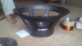
Nice, but before you even think about voice coils, you´ll need a big big magnetic system.
Think 220mm x 25mm at least (even better 2 stacked) , so you can fit a 100mm VC inside.
Then there´s the frame and "reconing parts" , but that´s the lesser problem.
The BIG problem for homebuilders is the magnetic structure ... and then he still has to magnetize it.
Think 220mm x 25mm at least (even better 2 stacked) , so you can fit a 100mm VC inside.
Then there´s the frame and "reconing parts" , but that´s the lesser problem.
The BIG problem for homebuilders is the magnetic structure ... and then he still has to magnetize it.
What are you trying to accomplish by doing this? Just to say you designed it? Or are you trying to re-invent the wheel and come up with something better than you can currently purchase?
Manufacturers put a ton of R&D into coil design, former material, heat exchange calculations etc etc. Then they test and retest and find problems. Fix and issue a v2 prototype etc. All this while trying to meet a price point.
So if this is a project just for fun, go for it.
But it seems you're coming on here to ask a very basic, "where do I start" question.
How are you going to choose parameters before knowing what your own specific goals from the driver / cabinet are?
The next point. An awesome driver specifically designed for one cabinet may not perform that well in another. What type of cabinet are you planning on using this in?
Do I understand correctly that you intend to build the woofer yourself? That is quite ambitious, and I wish you success! As for myself, I have built a few boxes that make noise but not of high quality. I don't use it for home theater, but my latest annoyance is that the low bass will rattle doors and other things in the house and I don't even feel it ... and I have my feet resting on the subwoofer ")
Thank you for your responses..i asked help because i want to build a woofer for my new system..brands ask for a lot of money..asking question here was for discussion purpose..for material selection i need your help. I know glass fibre type material is hard to find but it can withstand 300degrees of heat with physical displacement but cannot transfer heat and alluminium can transfer heat but this can lead to eddy current.. another problem i kn9w is weight of voil. The more the winding the more is weight.. thats why i m here asking for help
This is not for fun and is ambitious project.
And if only using fully perfect material produced by a company is a real deal then i guess DIYAUDIO would not be found!!
This is not for fun and is ambitious project.
And if only using fully perfect material produced by a company is a real deal then i guess DIYAUDIO would not be found!!
OK, I see you mean it, and have hardware to back it.
By the way, I´d love to see a couple pictures of your magnetizer.
Specially the yoke.
I guess you show a VC made by your supplier.
Fiberglass is great but hard to find and obviously your supplier has no experience with it, so ....
Actually aluminum former VC as that shown dissipate lts of heat.
Some tricks to increase power handling.
1) wind one layer straight on the winding form, still *without* the 0.1mm aluminum sheet former.
2) apply the aluminum sheet
3) wire the second layer.
So you end up with one layer inside, one outside, aluminum sheet in middle.
This maximizes heat transfer.
4) prepunch 5 mm holes around the aluminum former, to allow heat exchange.
5) the aluminum sheet must be black anodized , for maximum heat dissipation.
6) use a vented polepiece. I see you already took care of that.
7) ise a cardboard/paper dome, not a cloth type one, so it pushes air in/out through the VC holes.
Well, that´s basically it
PD: don´t forget those magnetizer pictures, specially the magnetizing yoke.
I guess it´s capacitove.
If so, how much capacitance and what voltage?
I´m building one 250mm capable myself
So far I have 2 , a 100 mm capable and a 150mm one.
PD2: aluminum is not very good as far as sound quality, it´s lossy and overdamps the system, but at those power levels there´s not much choice..
Can you get "black Kapton"?
OK, I see you mean it, and have hardware to back it.
By the way, I´d love to see a couple pictures of your magnetizer.
Specially the yoke.
I guess you show a VC made by your supplier.
Fiberglass is great but hard to find and obviously your supplier has no experience with it, so ....
Actually aluminum former VC as that shown dissipate lts of heat.
Some tricks to increase power handling.
1) wind one layer straight on the winding form, still *without* the 0.1mm aluminum sheet former.
2) apply the aluminum sheet
3) wire the second layer.
So you end up with one layer inside, one outside, aluminum sheet in middle.
This maximizes heat transfer.
4) prepunch 5 mm holes around the aluminum former, to allow heat exchange.
5) the aluminum sheet must be black anodized , for maximum heat dissipation.
6) use a vented polepiece. I see you already took care of that.
7) ise a cardboard/paper dome, not a cloth type one, so it pushes air in/out through the VC holes.
Well, that´s basically it
PD: don´t forget those magnetizer pictures, specially the magnetizing yoke.
I guess it´s capacitove.
If so, how much capacitance and what voltage?
I´m building one 250mm capable myself
So far I have 2 , a 100 mm capable and a 150mm one.
PD2: aluminum is not very good as far as sound quality, it´s lossy and overdamps the system, but at those power levels there´s not much choice..
Can you get "black Kapton"?
Thank you for your response.
At this time i cannot show u the images as i am out of town for a month.
I use capacitor bank to discharge...whats app me on +917588382278 i will give u all the details
Last edited:
And i want to use 4layers of coil so it will be 2layers inside and 2layers outside.
What do do u think of coil winding for 1800watts rms. What wire guage to use and what height would be preferable for winding the coil. Last i did was a 4.5inch voice coil winding height was 45mm 4layers. Output was good but weight of coil was way more for quick displacement. Can you put some lights on it??
Regards
Sabir Nadaf
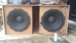
Give me your mail id. Or whats app number i will send you one video of my woofer. It gave me amazing Xmas of 1inches. But bass stroke was poor but vibration level was amazing. I drove it on 5000watts amp one transducer per channel. And they did not heat muvh after an hours test. Only some degrees above room temp.
You should measure the TSP's of the driver you've built to determine what needs to change.
Tell me how to do this without using a computer??
Tell me how to do this without using a computer??
You bought or built a magnetizer, maybe you should invest in a computer...
Obviously someone has a computer to do the sketchup work? REW can be used to measure the TSP's as well as acoustic measurements which you may find useful. Are you making the steel in house, or are you ordering motor + basket assembly's?
This makes me wonder if PD "invested" in tooling for those new baskets or if the vendor offered to sell PD some if their own new design. As usual it appears that there are no restrictions on proprietary parts coming out of asia.
Google "how to measure TS parameters" and you will find some explanation you like.
It requires a very well calibrated audio oscillator and a reasonably good audio voltmeter.
Since you are probably going to use a PC based oscillator , at least for the precise frequency measuring, you might as well go all the way and learn REW or some speaker measurement/testing software
Which does include measurement of TS parameters
It does exactly the same as the "manual" method, but "automates" frequency generation and measurement, and offers results in an easy to store and compare format, what´s not to like?
"Waste" (invest) a little time on it, you need it.
Later you will be able to measure your products, real world.
Simulation is nice and a powerful time saving tool, but nothing beats actual measuring.
Back to your coil, none in the World stands real 1000W RMS, even less 1800.
Fact is that to begin with those amps in no way have that much RMS power.
5000W ???? no way.
I work in live PA for big rock bands in our football stadiums, think 45000 people capacity,

a big favorite is Labgruppen "9000W" digital power amps.
Which *do* supply 9KW RMS ... for a few milliseconds ... but with continuous sinewave they self pad to some 1800/2000W RMS, go figure.
And that power is usually split between 2 PA (not car audio) 18" very good speakers, think JBL/RCF/Beyma/Faital .
Besides that, even a 1000W rating is misleading.
If pushed, they will admit that they are not burnt by a 1000W RMS amp ... which while true is not the same.
To begin with, at the frequencies these speakers are used, they are highly reactive, so actual power dissipated as heat is much lower.
Besides, they are designed to work with Voice Coils very hot ... which rises resistance (so it rises total impedance) a lot.
You are suggesting yours stand up to 300DegC .
Copper resistance rises with temperature, to the tune of 0.39% per DegC .
(300-25)*0.39%=275*0.39=107.25% resistance rise.
So with more than doubled resistance your Voice Coil will take less than half of what the SS power amp offers.
That´s how a speaker "resists 1000WRMS" ... by absorbing less than 500W , that´s how.
And even that is difficult to do.
In fact, serious makers include that data ... under the somewhat obscure name of "power compression".
Typical values between 2.5 to 3 dB ... what I´ve shown above.
Back to the coil you show above, what I see points to real , say, 200/300W RMS; if you perforate/vent it all around, do what I suggest above to push air along it, add some 50% to that .
Which might stand a nominal 1000W amp.
But for higher power handling:
1) forget 4 layers, you are heavily compromising dissipation
2) to put more copper in that gap, use edgewound rectangular copper ribbon.
3) get that copper insulated in a modern high technology "varnish" , something related to Kapton itself.
Or use thick anodized aluminum ribbon, where anodizing is the insulator.
4) research some adhesive which is good up to 400DegC , so it´s guaranteed good at 300 DegC under high mechanical stress.
5) if fact there is no 1000W or 1800W voice coil by itself, it may dissipate high power inside a speaker, moving through air like crazy, having that hot air blown away somehow and transmitting much of that heat to the frame and magnetic structure .
One big problem of Neo magnets is the small physical/thermal mass they have, so you´ll often see star/crown heavy finned heatsinks wrapped around them ... now you know why.
I´m very interested in what you are doing, and I warmly congratulate you on your efforts.
Please write me at: AudioEngineering (at) gmx (dot) com .
Juan Manuel Fahey .
PS: to American/Europe friends: I understand very well what sweetperfume is doing, Argentina is halfway between India and EuroAmerican Countries, here it still pays to actually make things and sell them to end users, what´s almost impossible there, because of the ferocious Asian outsourcing cost cutting against which it´s economically impossible to compete.
It requires a very well calibrated audio oscillator and a reasonably good audio voltmeter.
Since you are probably going to use a PC based oscillator , at least for the precise frequency measuring, you might as well go all the way and learn REW or some speaker measurement/testing software
Which does include measurement of TS parameters
It does exactly the same as the "manual" method, but "automates" frequency generation and measurement, and offers results in an easy to store and compare format, what´s not to like?
"Waste" (invest) a little time on it, you need it.
Later you will be able to measure your products, real world.
Simulation is nice and a powerful time saving tool, but nothing beats actual measuring.
Back to your coil, none in the World stands real 1000W RMS, even less 1800.
Fact is that to begin with those amps in no way have that much RMS power.
5000W ???? no way.
I work in live PA for big rock bands in our football stadiums, think 45000 people capacity,
a big favorite is Labgruppen "9000W" digital power amps.
Which *do* supply 9KW RMS ... for a few milliseconds ... but with continuous sinewave they self pad to some 1800/2000W RMS, go figure.
And that power is usually split between 2 PA (not car audio) 18" very good speakers, think JBL/RCF/Beyma/Faital .
Besides that, even a 1000W rating is misleading.
If pushed, they will admit that they are not burnt by a 1000W RMS amp ... which while true is not the same.
To begin with, at the frequencies these speakers are used, they are highly reactive, so actual power dissipated as heat is much lower.
Besides, they are designed to work with Voice Coils very hot ... which rises resistance (so it rises total impedance) a lot.
You are suggesting yours stand up to 300DegC .
Copper resistance rises with temperature, to the tune of 0.39% per DegC .
(300-25)*0.39%=275*0.39=107.25% resistance rise.
So with more than doubled resistance your Voice Coil will take less than half of what the SS power amp offers.
That´s how a speaker "resists 1000WRMS" ... by absorbing less than 500W , that´s how.
And even that is difficult to do.
In fact, serious makers include that data ... under the somewhat obscure name of "power compression".
Typical values between 2.5 to 3 dB ... what I´ve shown above.
Back to the coil you show above, what I see points to real , say, 200/300W RMS; if you perforate/vent it all around, do what I suggest above to push air along it, add some 50% to that .
Which might stand a nominal 1000W amp.
But for higher power handling:
1) forget 4 layers, you are heavily compromising dissipation
2) to put more copper in that gap, use edgewound rectangular copper ribbon.
3) get that copper insulated in a modern high technology "varnish" , something related to Kapton itself.
Or use thick anodized aluminum ribbon, where anodizing is the insulator.
4) research some adhesive which is good up to 400DegC , so it´s guaranteed good at 300 DegC under high mechanical stress.
5) if fact there is no 1000W or 1800W voice coil by itself, it may dissipate high power inside a speaker, moving through air like crazy, having that hot air blown away somehow and transmitting much of that heat to the frame and magnetic structure .
One big problem of Neo magnets is the small physical/thermal mass they have, so you´ll often see star/crown heavy finned heatsinks wrapped around them ... now you know why.
I´m very interested in what you are doing, and I warmly congratulate you on your efforts.
Please write me at: AudioEngineering (at) gmx (dot) com .
Juan Manuel Fahey .
PS: to American/Europe friends: I understand very well what sweetperfume is doing, Argentina is halfway between India and EuroAmerican Countries, here it still pays to actually make things and sell them to end users, what´s almost impossible there, because of the ferocious Asian outsourcing cost cutting against which it´s economically impossible to compete.
Google "how to measure TS parameters" and you will find some explanation you like.
It requires a very well calibrated audio oscillator and a reasonably good audio voltmeter.
Since you are probably going to use a PC based oscillator , at least for the precise frequency measuring, you might as well go all the way and learn REW or some speaker measurement/testing software
Which does include measurement of TS parameters
It does exactly the same as the "manual" method, but "automates" frequency generation and measurement, and offers results in an easy to store and compare format, what´s not to like?
"Waste" (invest) a little time on it, you need it.
Later you will be able to measure your products, real world.
Simulation is nice and a powerful time saving tool, but nothing beats actual measuring.
Back to your coil, none in the World stands real 1000W RMS, even less 1800.
Fact is that to begin with those amps in no way have that much RMS power.
5000W ???? no way.
I work in live PA for big rock bands in our football stadiums, think 45000 people capacity,
a big favorite is Labgruppen "9000W" digital power amps.
Which *do* supply 9KW RMS ... for a few milliseconds ... but with continuous sinewave they self pad to some 1800/2000W RMS, go figure.
And that power is usually split between 2 PA (not car audio) 18" very good speakers, think JBL/RCF/Beyma/Faital .
Besides that, even a 1000W rating is misleading.
If pushed, they will admit that they are not burnt by a 1000W RMS amp ... which while true is not the same.
To begin with, at the frequencies these speakers are used, they are highly reactive, so actual power dissipated as heat is much lower.
Besides, they are designed to work with Voice Coils very hot ... which rises resistance (so it rises total impedance) a lot.
You are suggesting yours stand up to 300DegC .
Copper resistance rises with temperature, to the tune of 0.39% per DegC .
(300-25)*0.39%=275*0.39=107.25% resistance rise.
So with more than doubled resistance your Voice Coil will take less than half of what the SS power amp offers.
That´s how a speaker "resists 1000WRMS" ... by absorbing less than 500W , that´s how.
And even that is difficult to do.
In fact, serious makers include that data ... under the somewhat obscure name of "power compression".
Typical values between 2.5 to 3 dB ... what I´ve shown above.
Back to the coil you show above, what I see points to real , say, 200/300W RMS; if you perforate/vent it all around, do what I suggest above to push air along it, add some 50% to that .
Which might stand a nominal 1000W amp.
But for higher power handling:
1) forget 4 layers, you are heavily compromising dissipation
2) to put more copper in that gap, use edgewound rectangular copper ribbon.
3) get that copper insulated in a modern high technology "varnish" , something related to Kapton itself.
Or use thick anodized aluminum ribbon, where anodizing is the insulator.
4) research some adhesive which is good up to 400DegC , so it´s guaranteed good at 300 DegC under high mechanical stress.
5) if fact there is no 1000W or 1800W voice coil by itself, it may dissipate high power inside a speaker, moving through air like crazy, having that hot air blown away somehow and transmitting much of that heat to the frame and magnetic structure .
One big problem of Neo magnets is the small physical/thermal mass they have, so you´ll often see star/crown heavy finned heatsinks wrapped around them ... now you know why.
I´m very interested in what you are doing, and I warmly congratulate you on your efforts.
Please write me at: AudioEngineering (at) gmx (dot) com .
Juan Manuel Fahey .
PS: to American/Europe friends: I understand very well what sweetperfume is doing, Argentina is halfway between India and EuroAmerican Countries, here it still pays to actually make things and sell them to end users, what´s almost impossible there, because of the ferocious Asian outsourcing cost cutting against which it´s economically impossible to compete.
That was very good info.. i will try to do the simulation
People in my country want product at very low cost and that of very good quality even to compete with a brand...i know i cannot have a genie lamp to do it in an instance but i want to do it...and as i m not a geek in this feild i need u guys to guide me. I will do whatever it takes to finalize this product Nd i want it to be worth it...i will google how to get the testing done.
I really dont know if i will succed in what i m doing but i will give it a try...
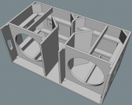
And one more thing , guys here say that every woofer is designed for a specific cabinet...can somebody elaborate it plz??
Every loudspeaker has specific TS (Thiele Small) parameters.And one more thing , guys here say that every woofer is designed for a specific cabinet...can somebody elaborate it plz??
Cabinets are designed for speakers with TS parameters falling within certain range, for instance, a driver with a Qts in the range of .3 to .8 is suited for a sealed enclosure, while a range of .18 to .7 is better for a ported enclosure. Other distinctions would be in general the cabinet port tuning (Fb) should not be much lower than the driver Fs. Horn loading puts more stress on a cone than bass reflex, requiring heavier cones, which require more magnet strength to control. The heavier cones reduce sensitivity, requiring more power for the same output, requiring better heat management to avoid power compression.
If you plug various driver's TS parameters into various cabinet designs using the Hornresp simulation program, you will see that certain drivers have a flatter response (less amplitude deviation) in a given design. Some cabinet designs are more tolerant of a wide variety of TS parameters, others require very specific parameters, a woofer designed for the specific cabinet.
Art
Last edited:
- Status
- This old topic is closed. If you want to reopen this topic, contact a moderator using the "Report Post" button.
- Home
- Loudspeakers
- Subwoofers
- need some guidance for building a P.A. subwoofer